DNR-X-1G Series RACKtangle and HalfRACK Systems
Chapter 5 84
PowerDNA Explorer
October 2018 www.ueidaq.com
508.921.4600
© Copyright 2018
United Electronic Industries, Inc.
Input/Output/Configuration/Initialization/Shutdown tabs switch between
displaying DIO pin reading of input state data, setting DIO output state,
configuring DIO as output or input, and settings for initial and shutdown states.
The Input tabs contain the following columns:
•Name is the channel (port) name, or a user-defined string.
•7:0 Input Values consist of 0 or 1 as read from the input pin.
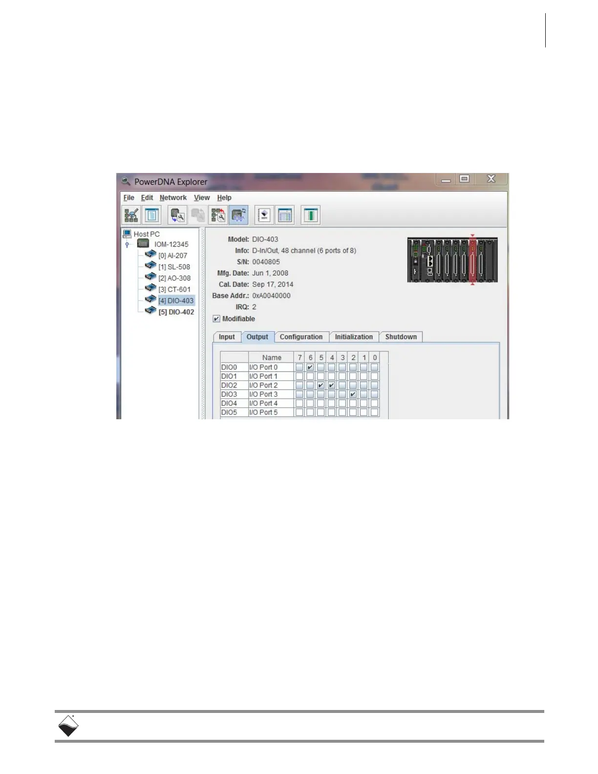
Figure 5-20. Example DIO-403 Outputs
Output tab sets the output value driven from the pin.
The Output tab contains the following columns:
•Name is the channel (port) name, or a user-defined string.
•7:0 Output values consist of the output state to be driven from the I/O
pin: select 0 (unchecked) or 1 (checked).
The settings in Figure 5-20 will cause output high values on DIO pin 6, pin 20,
pin 21, and pin 26. The settings will cause output low values on DIO pins 0, 1, 2,
3, 4, 5, 7, 16, 17, 18, 19, 22, 23, 24, 25, 27, 28, 29, 30, 31.
The rest of the pins are configured as inputs; input vs output configuration is set
under the Configuration tab.
 Loading...