DNR-X-1G Series RACKtangle and HalfRACK Systems
Chapter 2 19
The DNR-12-1G Series RACKtangle System
October 2018 www.ueidaq.com
508.921.4600
© Copyright 2018
United Electronic Industries, Inc.
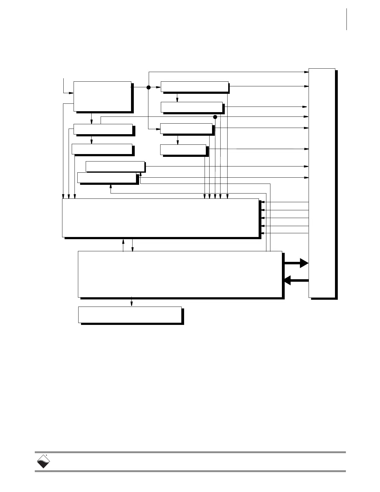
A functional block diagram of the DNR-POWER-DC Module is shown in
Figure 2-15 below.
Figure 2-15. Functional Block Diagram of DNR-POWER-DC Module
As shown in Figure 2-15, the DNR-POWER-DC Module operates as follows:
A 9-36 VDC voltage input (Vin) from an external source is connected to the
board through a replaceable slow-blow fuse. The board monitors the input
current and passes Vin to the DNR bus as Vout.
Vout also is connected to DC/DC converters that produce 24 VDC, 3.3 VDC and
1.5 VDC output voltages, which are also placed on the DNR bus. Both 3.3 and
1.5 VDC voltages are connected to low dropout regulators that, in turn, generate
the 2.5 VDC and 1.2 VDC output voltages on the bus. The 24 VDC source is fed
to a low dropout regulator that produces 8 VDC to drive the cooling fans (through
fan controller chips).
3.3V DC/DC
3.3V DC/DC
3.3V DC/DC
2.5V LDO
1.5V DC/DC
1.2V LDO
24V DC/DC
FAN3-4 CONTROL
8V FAN DC/DC
24-bit ADC (LTC2498) 13 sources: +2.5V, +2.5VNIC, 3.3V, +3.3VNIC,
+24Vm +24VNIC, +VIN, +1.5V, +1.2V, +8V FAN, I
in
,
TEMP1 (TCPOS), TEMP2 (TCNEG). Voltage sources use 1:23.1
dividers on the front end, except for the Vin, which uses a 1:45.3
divider.
Standard NIC-logic plus:
Access to ADC data readings
Fan 1-2 and 3-4 ON/OFF control
Fan ON/OFF status
12 LEDs ON/OFF control
LED block – 12 status LEDs
Input Current
Monitor
+2.5V NIC
DNR Bus Connector
+3.3V NIC
+24V NIC
TEMP1
TEMP2
FAN1-2 CONTROL
Input Voltage Source
9-36 VDC @ 80 W max.
1.2V
1.5V
24V
3.3V
2.5V
24V
8V
Vin
 Loading...