DNR-X-1G Series RACKtangle and HalfRACK Systems
Chapter 5 81
PowerDNA Explorer
October 2018 www.ueidaq.com
508.921.4600
© Copyright 2018
United Electronic Industries, Inc.
5.2.4.2 I/O Device /
Board Settings
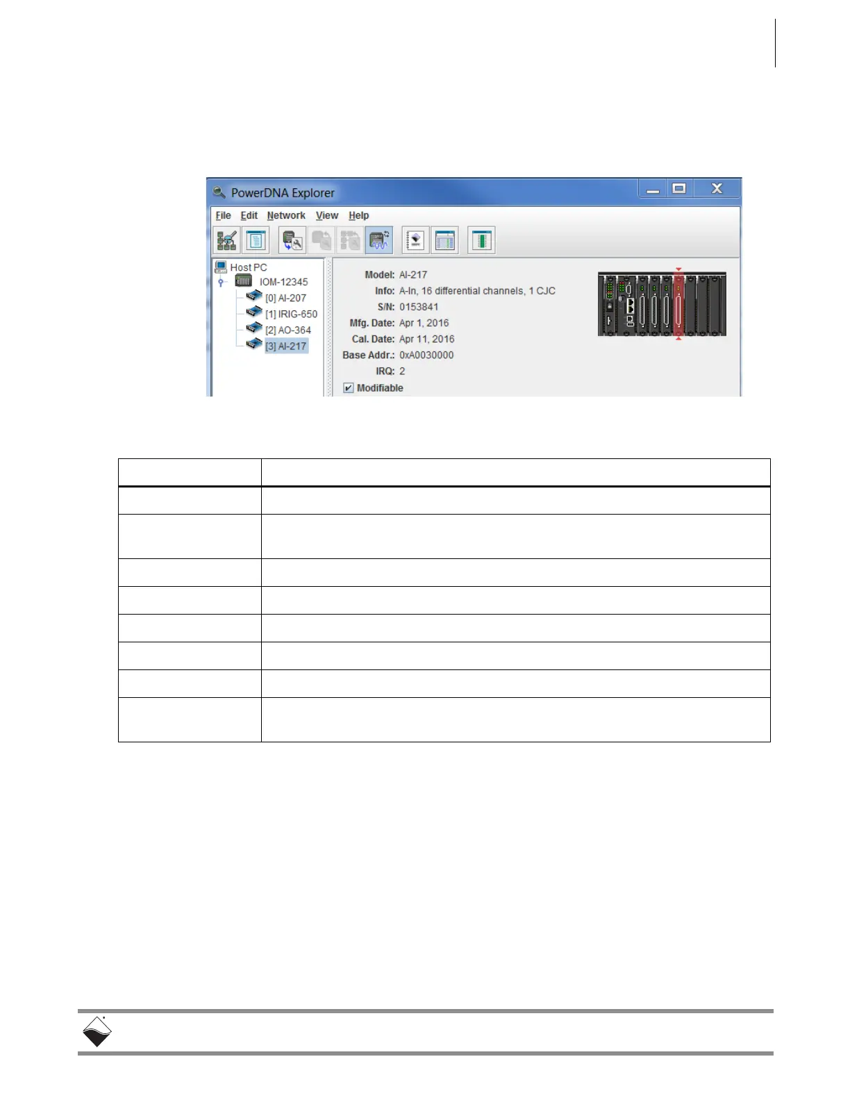
Figure 5-17 provides an overview of the screen for displaying I/O device
settings. Setting options vary for I/O boards on a per-board basis. The example
below show settings for the AI-217 analog input board.
Figure 5-17. Example of I/O Device Settings
Field Description
Model shows the model number of the device
Info shows summary of key features of the device: A for analog, D for digital, In for
input, Out for output, and the number of channels available
S/N shows the serial number of the device
Mfg. Date shows the manufacturing date
Cal. Date shows the date of the last calibration done
Base Address shows the base address of the board in the IOM system
IRQ shows which interrupt is assigned to the board
Modifiable provides a checkbox which, when unchecked, prevents parameters from being
changed
Table 5-2 Fields and Descriptions for I/O Device Settings Panel
 Loading...