DNR-X-1G Series RACKtangle and HalfRACK Systems
Chapter 2 24
The DNR-12-1G Series RACKtangle System
October 2018 www.ueidaq.com
508.921.4600
© Copyright 2018
United Electronic Industries, Inc.
2.8 DNR-Buffer
Module
The DNR-BUFFER Module provides buffering between the CPU and I/O board
address/control/clock lines, which functions as described in Figure 2-16.
Although the module may not always be required, it is included to provide an
extra margin of safety against loss of data.
2.9 DNR I/O
Boards
All standard cube-based PowerDNA I/O boards are also available as rack-
based PowerDNR boards. A typical PowerDNR board is functionally identical to
its corresponding PowerDNA version. The only difference between them is the
physical mounting arrangement. PowerDNR modules are designed for insertion
into the DNR-6 or DNR-12 enclosure; PowerDNA modules can be inserted only
into a PowerDNA Cube.
Refer to the datasheets and user manuals for detailed electrical specifications,
board descriptions, and user instructions for I/O boards. These documents are
available on the UEI website at www.ueidaq.com.
2.10 DNR-12-1G
DC Power
Thresholds
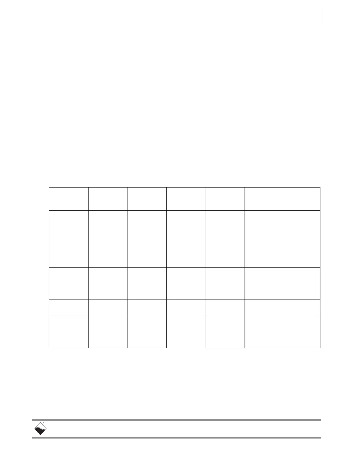
Table 2-1 lists the DC power threshold specifications for DNR-12-1G 12-slot
RACKtangle systems.
NOTE: A DNR-12-1G CPU/NIC core module consumes only 70mW when Vin is
below 7V.
Table 2-1 DC Power Thresholds for DNR-X-1G RACKtangle and HalfRACK systems
Backplane
Power Rail
Voltages
Turn-on
Voltage, V
1
Reset
Voltage, V
Turn-off
Voltage, V
2
Notes
Logic power
supply
+3.3V, +2.5V,
+1.5V, +1.2V
7.5 7.2
(When Vin is
below 7.2V, a
voltage reset
puts all
boards into
reset mode.)
7.0 Supplies power to all CPUs
and FPGAs. DNR can com-
municate with Ethernet
when CPU is functional
Analog power
supply
+24V 8.5 - 7.8 Analog power supply is
used as a regulated source
for on-board DC/DCs on
most boards
Fan power
supply
+12V 8.5 - 8.4
On-board
DC/DCs that
use input
power
+VIn 7.8-8.8 - 7.5-8.5 Varies with board type.
1. Turn-on, V: The value of Vin at which the corresponding DC/DCs are turned on.
2. Turn-off, V: The value of Vin at which the corresponding DC/DCs are turned off.
 Loading...