DNR-X-1G Series RACKtangle and HalfRACK Systems
Chapter 4 58
Installation and Configuration
October 2018 www.ueidaq.com
508.921.4600
© Copyright 2018
United Electronic Industries, Inc.
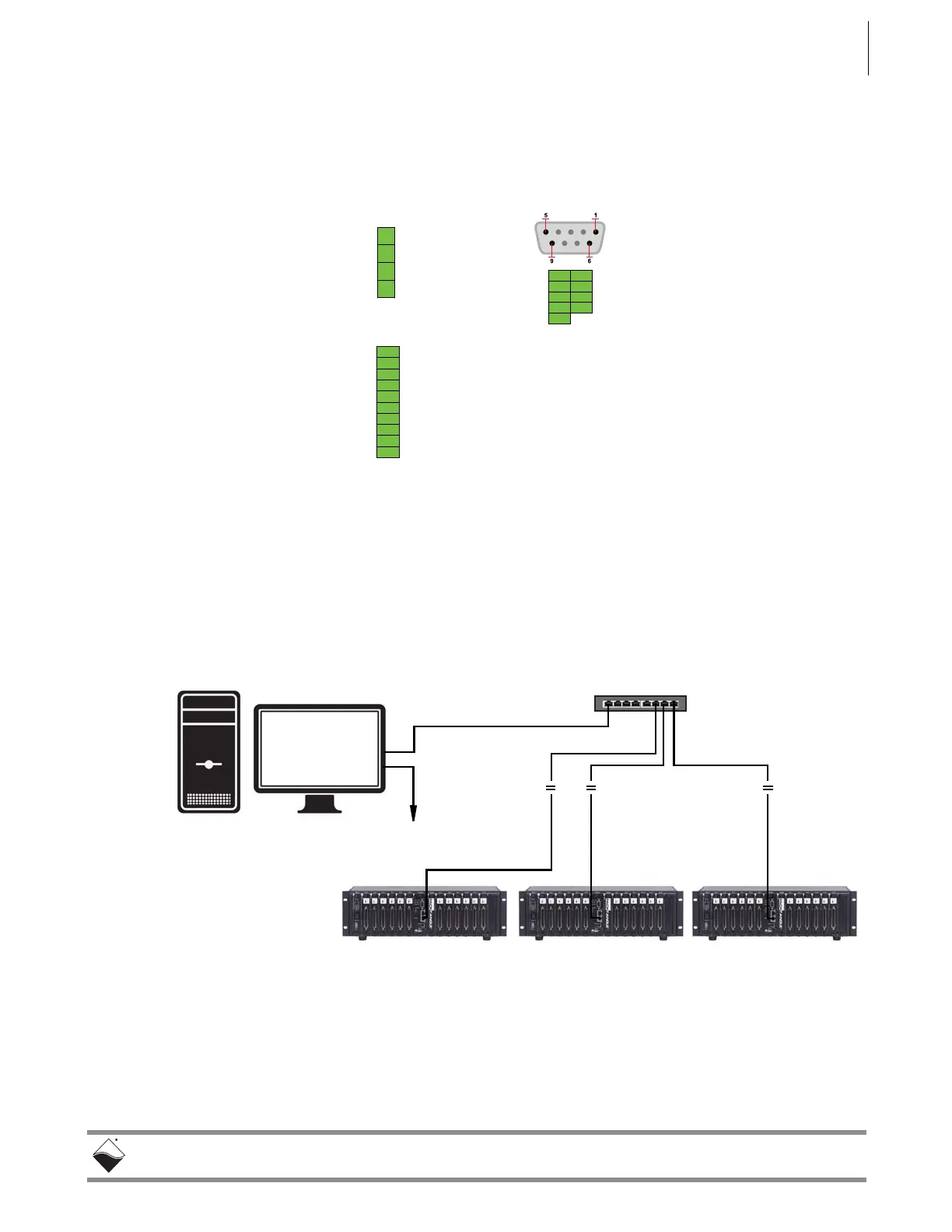
4.7.2 Pinout
Diagrams
Pinout diagrams for the power molex, synchronization port, and RS-232 serial
port connectors are shown below in Figure 4-15.
Figure 4-15 DNR-X-1G Pinout Diagrams
4.7.3 Network
Wiring
1000Base-T Wiring Configurations
A typical wiring configuration for a 1000Base-T network is shown in the following
figure.
Figure 4-16. System Configuration with LAN Switch
Refer to “Network Configuration” on page 44 for more configuration options.
4321
+VIN
GND
GND
+VIN
Power In
1
(molex)
Synchronization
1 +5 V
2 +5 V
3 Gnd
4 Sync Out 2
5 Gnd
6 Sync In 2
7 Gnd
8 Sync Out 1
9 Gnd
10 Sync In 1
16
TXD– 27
RXD– 38
49
GND– 510
Serial (RS-232)
1
Mating connector and pins are o-the-shelf items:
Molex PN 39-01-4040 (connector)
Molex PN 44476-3112 (pins)
To diagnostic ports
via LAN switches
 Loading...