DNR-X-1G Series RACKtangle and HalfRACK Systems
Chapter 2 22
The DNR-12-1G Series RACKtangle System
October 2018 www.ueidaq.com
508.921.4600
© Copyright 2018
United Electronic Industries, Inc.
2.7.1 Device
Architecture
of DNR Core
Module
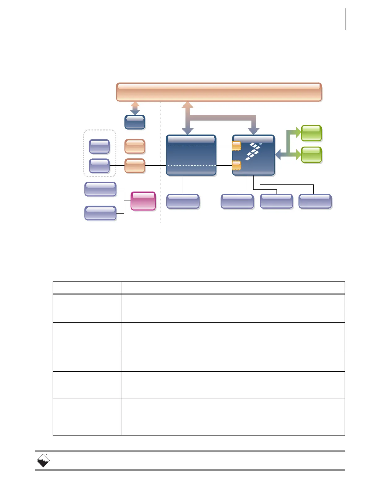
Figure 2-17 shows the architecture of the DNR-CPU-1000 Series Core
Modules:
Figure 2-18. FreeScale PowerPC CPU/NIC Controller Architecture
The core of the system is a Freescale PowerPC MPC8347 or MPC8347E 32-bit
400 MHz processor, which controls the following components:
MAC
MAC
PPC 8347
DC/DC
9-36V DC Input
Power Out
Power In
SD Card RS-232
32-bit 66-MHz bus
RJ-45
RJ-45
PHY
PHY
RTC
DDR2
FLASH
MII
1000-BASE-T
MII
FPGA
USB 2.0
USB 2.0
,(((QHWZRUNV\QFKURQL]DWLRQVXSSRUWRQDQG&38YHUVLRQV
Table 2-2 Components in PowerDNR Core Module (DNR-CPU-1000 Series)
Item Description
NIC1:
Primary Network
Interface MII Port
The NIC1 port provides communication between the DNR system and the
primary LAN network.
NIC2:
Diagnostic Network
Interface MII Port
The NIC2 port provides access to the DNR system for monitoring system health
during operation, using a separate diagnostic port. This port may also be
assigned as the primary Ethernet port if NIC1 is not available for use.
RS-232 Port The RS-232 port provides a serial communication link between the DNR-X-1G
system and a standard RS-232 terminal.
USB 2.0 Dual Port
(Controller and Slave)
The USB A and B ports are not supported on DNR-X-1G (hosted) systems
(only supported on UEIPAC, UEISIM, UEIModbus, and UEIOPC-UA
deployments).
32 MB or 128 MB
Flash Memory
1
DNR-X-1G (-00/-01) systems provide 32 MB of flash memory (DNR-CPU-
1000).
DNR-X-1G-02 systems provide 32 MB of flash memory (DNR-CPU-1000-02).
DNR-X-1G-03 systems provide 128 MB of flash memory (DNR-CPU-1000-03).
 Loading...