DNR-X-1G Series RACKtangle and HalfRACK Systems
Chapter 3 33
The DNR-6-1G Series HalfRACK System
October 2018 www.ueidaq.com
508.921.4600
© Copyright 2018
United Electronic Industries, Inc.
3.5 DNR-6 Power,
NIC/CPU, and
I/O Boards
LEDs &
Controls
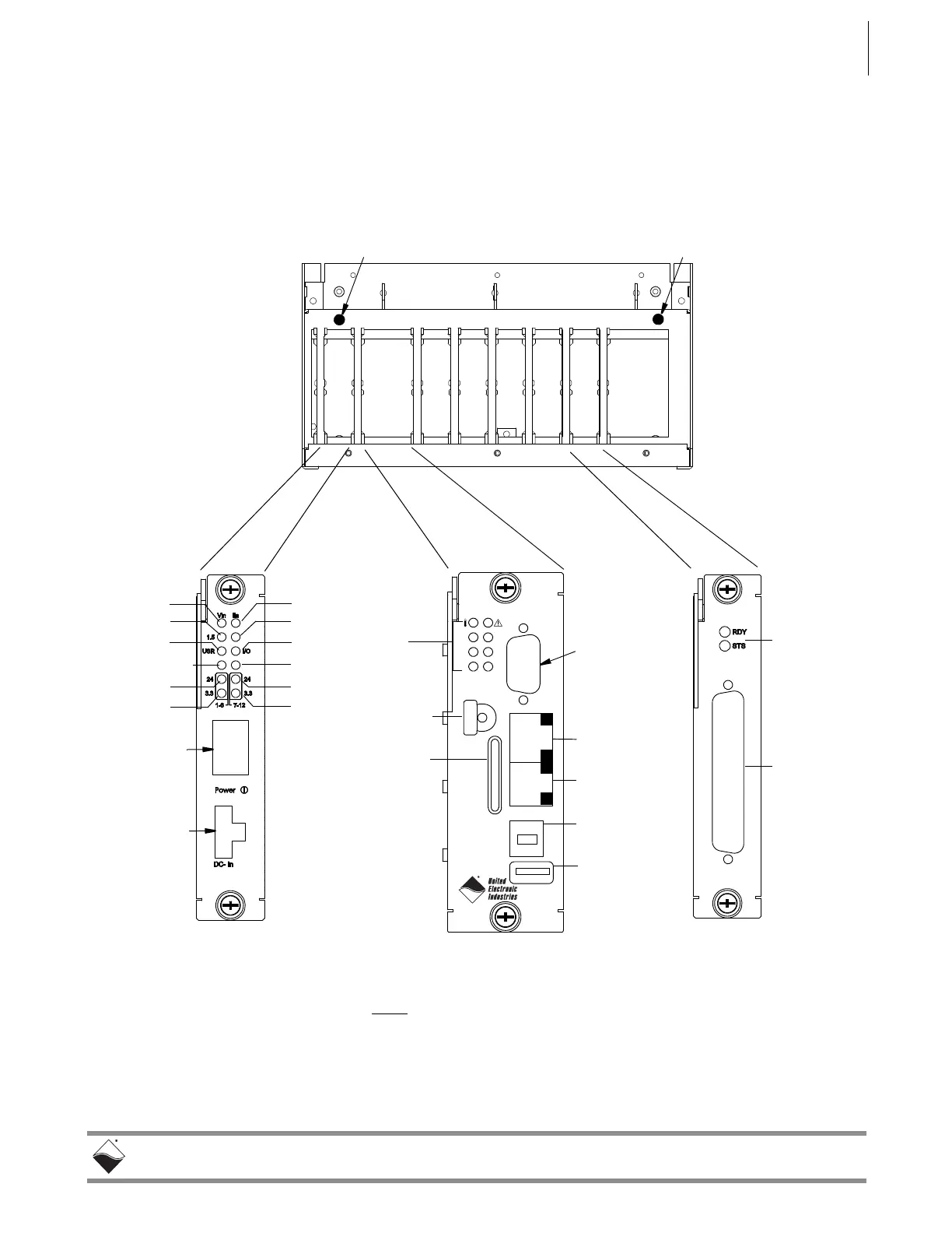
DNR-6-1G LED indicators are illustrated in Figure 3-7.
Note that modules used in both DNR-6 and DNR-12 systems are identical,
except that the DNR-6 enclosure only accepts six I/O boards. The power, CPU,
and I/O board LEDs are individually described in “DNR-12 Power, NIC/CPU, and
I/O Boards LEDs & Controls” on page 14.
Figure 3-7. DNR-6-1G System Front Panel Arrangement
SD Card
USB B
USB A
NIC 1
NIC 2
Sync/Reset
RS-232
3.3
24
COM
USRR/W
PG
POWER
CPU/NIC
Module 1
Module 2
Module 3
Module 4
Module 5
Module
DNR-POWER-DC
Typical
I/O Board
Serial Port
Connector
Status
LEDs
NIC1 Port
NIC2 Port
Temp1 Sensor
Temp0 Sensor (on backplane)
Status
LEDs
DB
Connector
Vin
1.5V
User
Overtemp
24V
3.3V
Iin
I/O
Fan
24V
3.3V
(7-12)
(1-6)
Power
Conn.
PowerDNR
PowerDNR
1.2V
Switch
0n/off
Power
DB-9
ATT Indicates error when red
R/W Flashes when bus is active
COM Flashes when SD Card is read/written
PG Indicates presence of valid power input
LEDs
DC/DC Module
(Single Slot Model)
USB 2.0
USB 2.0
Controller
DNR-CPU-1000/-XX
CPU/NIC Module
PowerDNR
Slave Port
Port
Sync
Conn/PB
SD Card
Slot
Module 6
(dual width)
 Loading...