DNR-X-1G Series RACKtangle and HalfRACK Systems
Chapter 5 71
PowerDNA Explorer
October 2018 www.ueidaq.com
508.921.4600
© Copyright 2018
United Electronic Industries, Inc.
STEP 3: Click Network >> Scan Network to scan the LAN for DNR-X-1G systems or
cubes within the range specified in the previous step.
One or more gray icons will display in the left-hand-side of the screen. If no icons
are displayed, refer to the Troubleshooting section in the previous chapter
(Section 4.5).
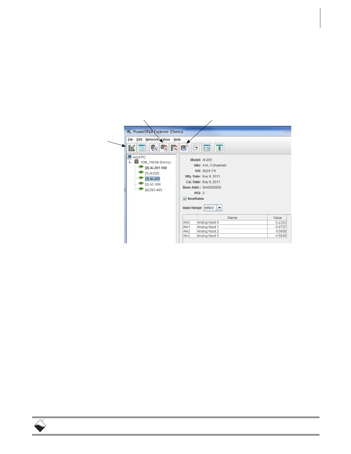
STEP 4: Double-click an icon to display its information and list the I/O boards:
Figure 5-3. Typical Screen for Analog Input Board
The screenshot above is from the PowerDNA Explorer Demo. The “demo” is a
simulator for users without hardware or for new users who want to explore the
PowerDNA Explorer program without reading/writing to real hardware. Run this
program and hover your mouse over the buttons to read the tool-tips and learn
through interacting with the program.
Some quick notes:
To read from a board, click the fourth-to-last button: “Start Reading Input
Data”
To write to the board, change a value and click the fourth button with the
red arrow on top of the chassis: “Store Configuration”. The icon with the
blue arrow on it restores the configuration.
To change the IP address, change the number, deselect the field, and
“Store Configuration”. Take care not to set the IP Address to outside of the
network’s configuration subnet -or- to an IP address that is currently in
use, as the system will then become unreachable.
To obtain a hardware report, click View >> Show Hardware Report.
Refer to Section 5.2 for more descriptions of the PowerDNA Explorer Window.
Scan Network
Store Configuration Start Reading Input Data
 Loading...