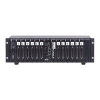
DNR-X-1G Series RACKtangle and HalfRACK Systems
Chapter 2 17
The DNR-12-1G Series RACKtangle System
October 2018 www.ueidaq.com
508.921.4600
© Copyright 2018
United Electronic Industries, Inc.
2.6 DNR-POWER-
DC Module
The DNR-POWER-DC Module is a dedicated DC/DC source and control
module available only for use with a PowerDNR rack enclosure. It is always
mounted in the leftmost slot of the DNR chassis and is recognized on the
PowerDNR bus with an ID of 0x020 at address 0xA00C0000.
The non-isolated side (NIS) logic complies with full common logic interface (CLI)
implementation. The key features of the DNR-POWER Module are:
• Input power — 9-36 VDC 80W maximum, protected by resettable fuses
and EMI chokes
• Power supply on/off switch (with guard)
• Output power sources (all with greater than 90% efficiency)
24V, 1A (24W)
3.3V, 5A (16.5W, including the 2.5V derived voltage)
2.5V, 3A (derived from 3.3V source)
1.5V, 5A, (7.5W, including the 1.2V derived voltage)
8V, 0.5A (4W for fans)
• DC/DC for 24V, 3.3V, and 1.5V are synchronized from the single spread-
spectrum clock source in the CPU/NIC Module for lower EMI noise level
• Fan control (Forced ON) and status ON/OFF
• Monitoring and LED indicators (1% accuracy, 0.25Hz update rate)
for:
– All output voltages
– Input current for the 9-36VDC for the DNR Enclosure
– All voltages from the NIC Module (24V, 3.3V, 2.5V)
– Temperature of the DNR backplane (2 sensors)
• Onboard FPGA logic chip is CYCLONE EP1C3/C6T144
• TI MSP4300 microcontroller used for logic reprogramming
• Input-Output connector is a 128-pin component that provides 9-36VDC
for all modules from an external power source

 Loading...