Chapter 4 _______________________________________________________________ Installation
VAISALA_______________________________________________________________________ 97
Connecting Sensor Cables
Connect the sensor cables to the enclosure after mechanically installing
the sensors. All sensors, power supplies, and communication devices are
connected to the system using environmentally-sealed connectors. All the
connectors are labeled and located on the bottom flange of the electronic
enclosure. See also Appendix A, Wiring Diagrams, on page 263 for an
overview of AWS330 wiring.
NOTE
Be careful not to bend the connector pins when connecting the cables.
1012-199
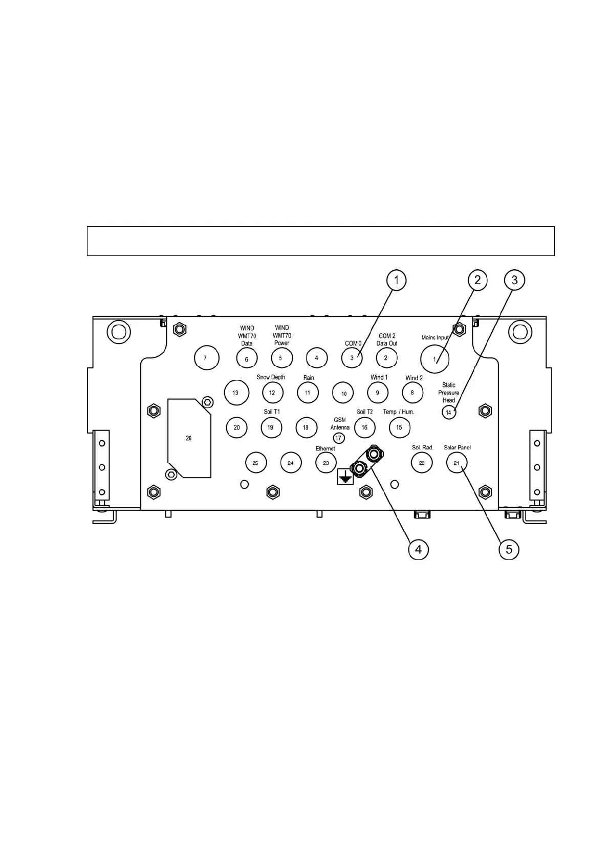
Figure 53 Connector Flange of the Enclosure
The following numbers refer to Figure 53 above:
1 = Maintenance terminal COM0 connector
2 = AC (mains) input power connector
3 = Static pressure head tube
4 = Grounding rail for common grounding point
5 = Solar panel connector
Static Pressure Head
Static pressure head (number 3 in Figure 53 above) minimizes field-
induced error in pressure measurement.