User's Guide ______________________________________________________________________
210 _________________________________________________________________ M211296EN-A
Visual Check
Open the enclosure and check that all the equipment is present. Check
that the QML logger, power supply, and communication devices are
connected properly. Remove the cover of the logger for visually checking
the CPU board and other components located under the cover. In Figure
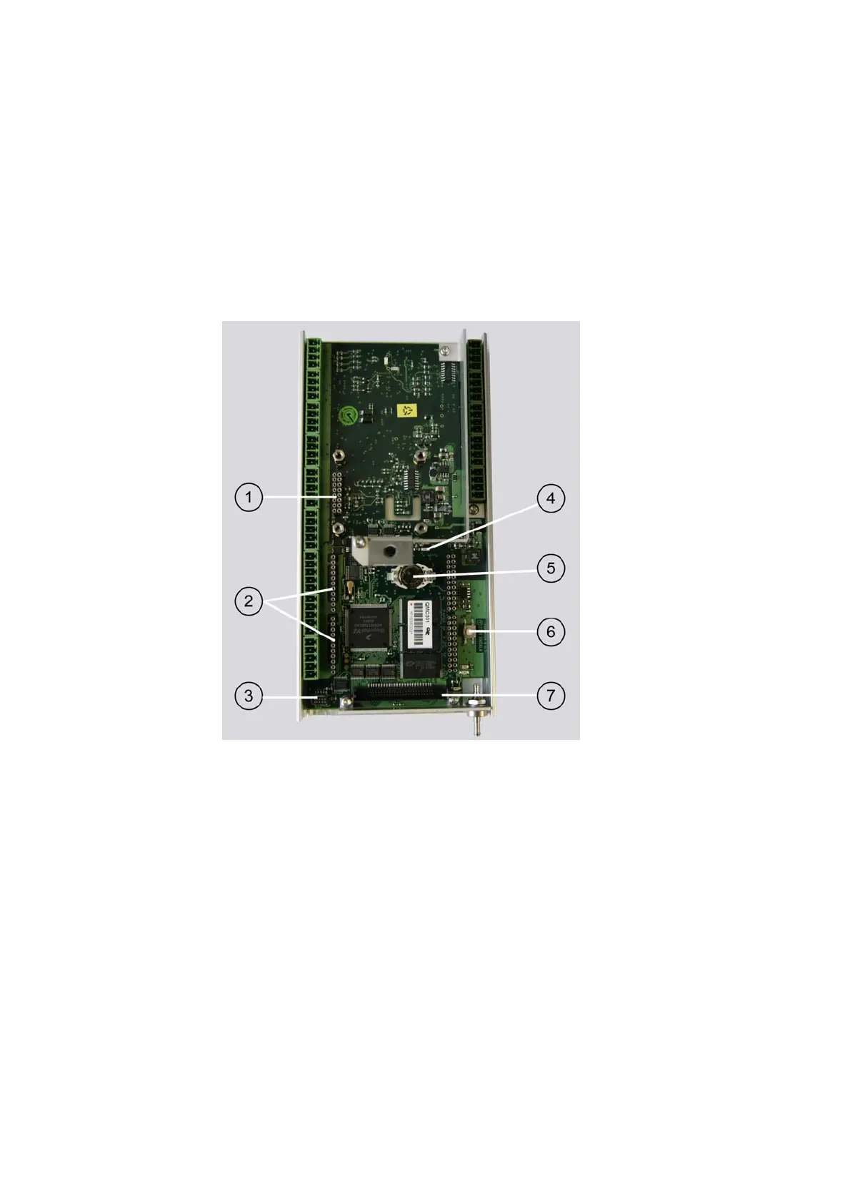
120 below, the logger is shown without the cover and the optional
communication modules.
1004-120
Figure 120 QML Logger without Cover
The following numbers refer to Figure 120 above:
1 = Pressure sensor
connector
2 = Communication module places MOD1 and MOD2
3 = SPI connector
4 = Status LED (green)
5 = Lithium battery for RTC
6 = Reset button
7 = CF Card connector