Model Description
‑65 65 mm (2.5 in)
‑80 80 mm (3 in)
‑100 100 mm (4 in)
‑125 125 mm (5 in)
‑150 150 mm (6 in)
Counter flange options
‑SN Steam nozzle, G¼ thread female
‑WP Pressurized water nozzle, G¼ thread female
‑WN Water nozzle, G¼ thread female
‑PG Varivent blind flange type N
1) Includes one 1.5 in type N blind flange with 2.5 in EPDM gasket and 2.5 in Varivent clamp Type N
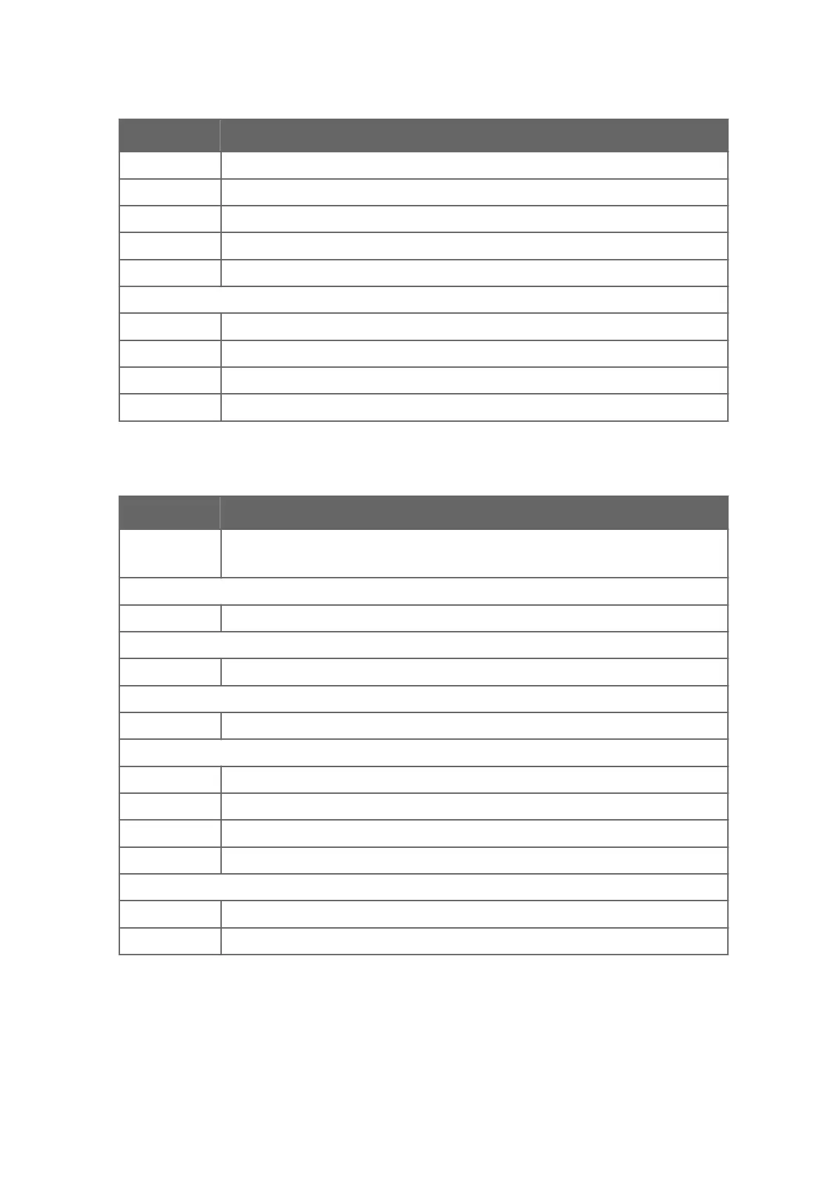
Table 18 Side flow cells, connection sanitary clamp 2.5 in
Model Description
SFC Side flow cell
1)
Sensor connection
‑H Sanitary clamp, 2.5 in
Material of construction
SS AISI 316 L
Process connection
‑H Sanitary clamp
Pipe section diameter
10 25 mm (1 in)
15 40 mm (1.5 in)
20 50 mm (2 in)
25 65 mm (2.5 in)
Flow cell inlet and outlet orientation
‑90 Elbow, 90 ° bend
‑180 Straight pipe, 180 °
1) Includes one 2.5 in EPDM gasket and 2.5 in sanitary clamp.
Chapter 10 – Sensor specifications
105

 Loading...


