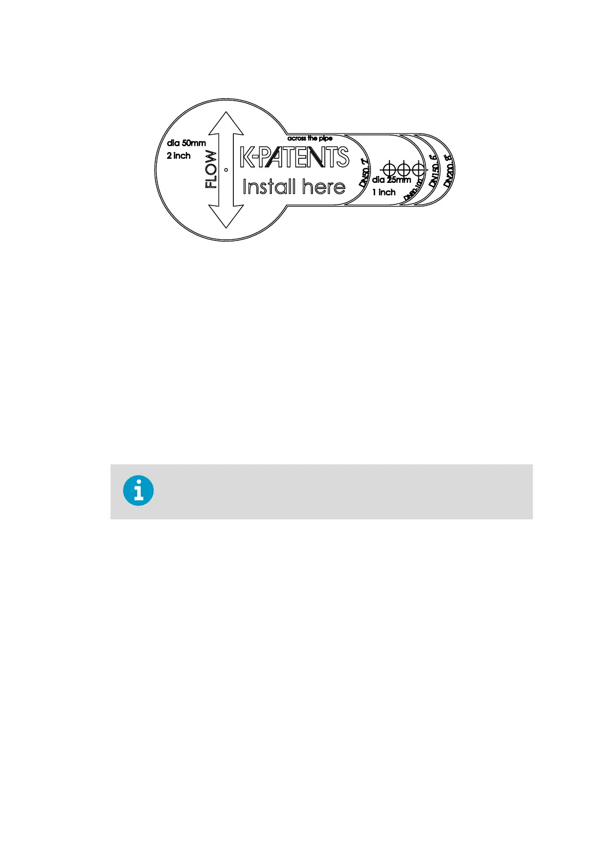
Figure 100 Safe-Drive isolation valve installation guide sticker
The welding steps are as follows, see Figure 101 (page 180) or Figure 102 (page 181):
1. Clean the surface of the pipe around the installation area and place the guide sticker
across the pipe. Make sure that the flow marker is parallel to the pipe and points to the
correct flow direction.
2. Disassemble the isolation valve for welding to avoid thermal damage to the isolation
valve sealing.
3. Drill 50 mm (2 in) and 25 mm (1 in) holes to pipe and cut the metal away between the
holes.
4. Weld the isolation valve according to MTG472 or MTG2149, see Figure 101 (page 180) or
Figure 102 (page 181).
5. Reassemble the isolation valve.
Make sure that you position the isolation valve handle and the large bayonet tooth
so that they are on top.
6. Tighten the four M10 nuts to the torque 35 Nm (26 lbf ft).
Chapter 11 – Safe-Drive
179

 Loading...


