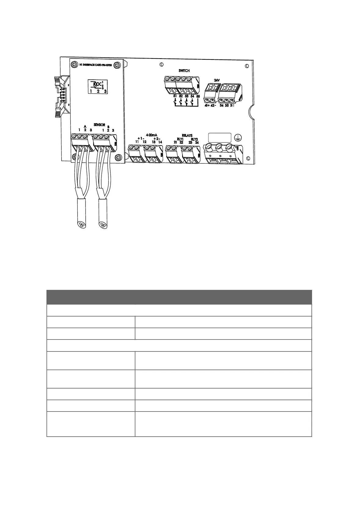
Figure 10 Motherboard (24 VDC)
T
he following table describes the terminals on the H1 interface card PR‑10701 and on the
transmitter motherboard PR‑10600.
Terminal Usage
On H1
A 1 2 3 Connection for Sensor A, signal wires (1, 2), cable shield (3).
B 1 2 3 Connection for Sensor B, signal wires (1, 2), cable shield (3).
On motherboard
11 12 4 … 20 mA output 1, positive (11), negative (12), max. load 1000 Ω,
galv
anically isolated.
13 14 4 … 20 mA output 2, positive (13), negative (14), max. load 1000 Ω,
galv
anically isolated.
21 22 Relay 1, one contact output, max. 250 VAC, max. 3 A.
23 24 Relay 2, one contact output, max. 250 VAC, max. 3 A.
31 32 33 Power, L (31), N (32), protective earth (33), 100 … 240 VAC, 50 … 60 Hz,
fuse with v
oltage 250 VAC, max. size 10 A and speed slow. An external
power switch is mandatory.
PR-23 Series User Guide
IM-EN-PR23-E
32

 Loading...


