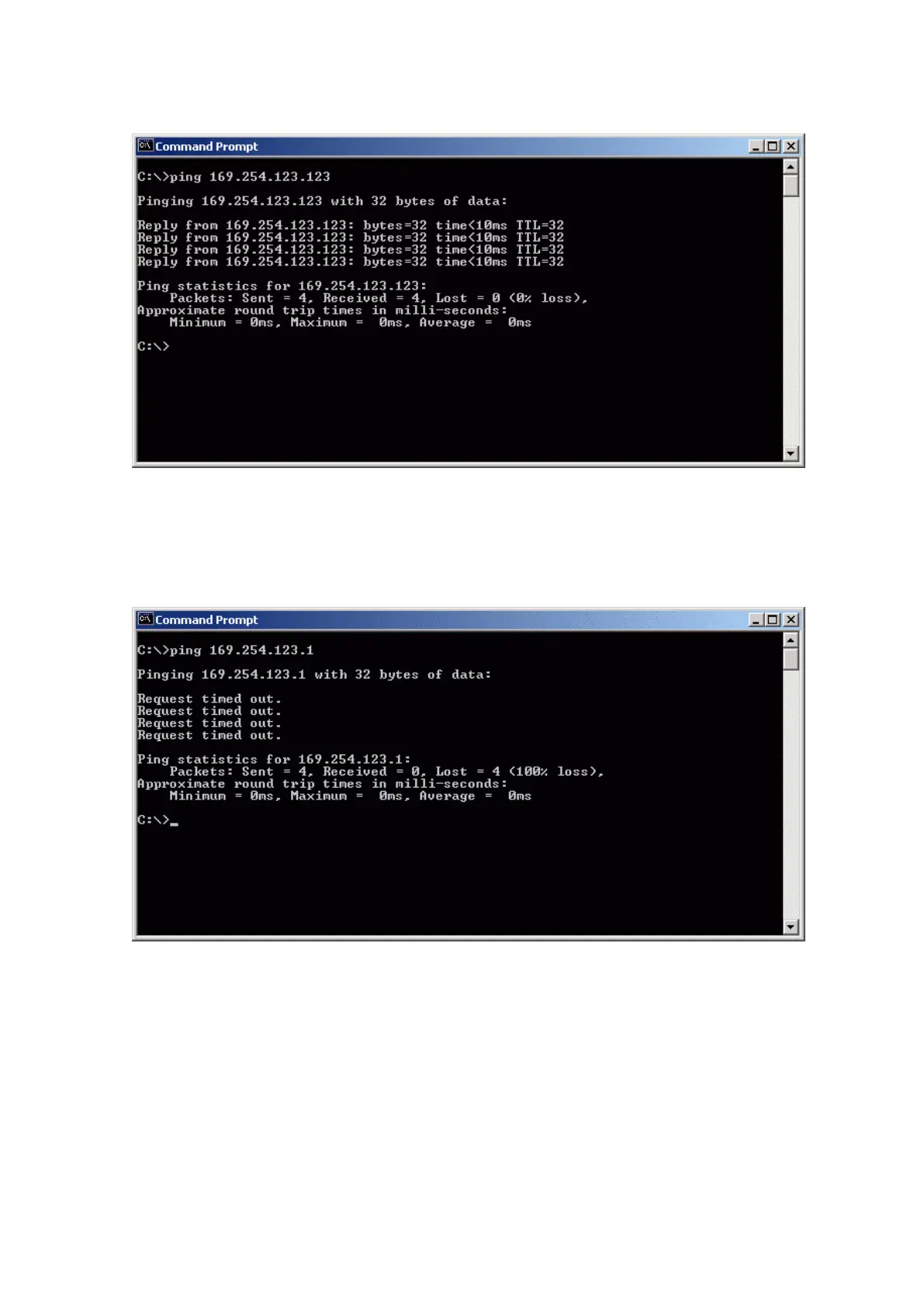
Home
Vaisala
Measuring Instruments
PR-23 Series
Vaisala PR-23 Series User Manual
4
of 1
of 1 rating
272 pages
Give review
Manual
Specs
To Next Page
To Next Page
To Previous Page
To Previous Page
Loading...
Figure 12
7 Ping OK
15.3.
1
T
roubleshooting c
onnection
Figure 128 Ping err
or message
If y
ou get a
ping
error message
, check your c
onnections.
Open the D
TR co
v
er and front panel and check the diagnostic LEDs of the Ethernet
connect
or
, see
Connecting Ethernet cable (page 229)
.
Chapter 15 – Ethernet connection
specifica
tion
233
234
236
Table of Contents
Default Chapter
3
Table of Contents
3
1 About this Document
13
Version Information
13
Documentation Conventions
13
Trademarks
14
Patent Notice
14
Table 2 PR-23 Patents
14
2 Product Overview
15
Safety
15
Storage Conditions, Packaging and Transportation
17
Refractometer Models
17
Refractometer Sensor
17
3 Mounting Sensor
19
Choosing Sensor Mounting Location
19
Mounting Guide
21
Pipe Mounting Checklist
22
Checklist for Mounting in Tank, Vessel or Large Pipe
22
4 Indicating Transmitter DTR
23
Indicating Transmitter Enclosure
23
Mounting Indicating Transmitter
25
Electrical Connections
26
Interconnecting Cable
26
Indicating Transmitter Dimensions and Mounting Feet Measures
26
Connecting Sensor
27
Connecting Indicating Transmitter
29
Figure 10 Motherboard (24 VDC)
34
Power Terminals for AC Power
35
Power Terminals for 24 VDC Power
35
Relay Connections
36
Reset Button
38
5 Prism Wash Systems
39
Prism Coating
39
Prism Wash
39
Recommended Wash Pressures and Times
39
Table 3 Wash Medium Parameters for Integral Wash Nozzles in
40
Table 4 Wash Medium Parameters for Flow Cell Wash Nozzle AFC
40
Table 5 Wash Medium Parameters for Safe-Drive Isolation Valve
40
Prism Wash Systems
41
Figure 12 Prism Wash System for Steam (Non-Sanitary)
41
Figure 13 Sanitary Prism Wash System for Steam
42
Figure 14 Pressure Reducing Valve PR-3341-J
43
Figure 15 Install Strainer Horizontally
44
Figure 16 Wiring for a Prism Wash System for Steam
45
Figure 17 Prism Wash System for High Pressure Water
46
Figure 18 Wiring for Prism Wash System for High Pressure Water
47
Prism Wash Nozzles
48
Figure 19 Wash Nozzles for Flow Cell AFC-HSS-XXX-XX-NC
48
Figure 20 Process Connection of Wash Nozzle in Flow Cell
49
Table 6 Prism Wash Nozzle Selection
49
Figure 21 Mounting of Wash Nozzle for Sanitary Probe
50
Figure 22 Mounting of Wash Nozzle for Process Refractometer PR-23-GP
51
6 Startup and Use
52
Startup
52
Initial Check
52
Figure 23 Main Display Alternatives
52
Calibration Check
53
Testing Prism Wash
53
Using Indicating Transmitter
53
Keyboard Functions
54
Figure 24 DTR Keyboard and Main Menu for Sensor B
54
Display Setup
55
Figure 25 Display Setup Menu
55
Figure 26 Main Display Format Selection
56
Viewing System Information
57
Viewing Sensor Status
57
Optical Image with IDS
57
Figure 27 System Description
57
Figure 28 Optical Images with IDS
58
Figure 29 Slope Graph with IDS
58
Optical Image with VD
59
Diagnostic Values
59
Figure 30 Optical Images with VD
59
Temperature Measurement
60
Sensor Head Humidity
60
Sensor Verification
60
7 Configuration and Calibration
61
Configuring Output Signal Damping
61
Exponential Damping
61
Linear Damping
62
Figure 31 Exponential Damping
62
Slew Rate Limit
63
Figure 32 Linear Damping
63
Configuring Output Signal Hold Functionality
64
Figure 33 Slew Rate Damping
64
External Hold
65
Hold During Wash
65
Tolerance Time
65
Figure 34 Effect of Tolerance Time on Output
66
Hold Source Interactions
66
QF Threshold
66
Figure 35 Damping Stops During Hold
67
Hold and Signal Damping
67
Hold Functions with DD-23
67
Configuring Refractometer System
68
Configuring Relays
68
Figure 36 Relay Menu for Relay 1
68
Configuring Input Switches
70
Configuring Ma Outputs
72
Figure 37 Output Menu for Ma Output 1
73
Calibrating Concentration Measurement
74
Figure 38 Default Ma Output Values
74
Figure 39 Concentration Calibration Layers
75
Chemical Curve
76
Selecting Display Units and Display Decimals
76
Table 7 Chemical Curve Parameters
76
Field Calibration
77
Direct BIAS Adjustment
78
Entering Field Calibration Parameters
78
Figure 40 Using FIELD SAMPLE Soft Key
78
Configuring Prism Wash
79
Wash Cycle
79
Figure 41 Automatic Prism Wash Cycle
79
Figure 42 Wash Logic
81
Figure 43 Wash Cycle
83
Setting Prism Wash Parameters
84
8 Regular Maintenance
86
Checking Sensor Humidity Level
86
Checking Prism and Prism Gaskets
86
9 Troubleshooting
87
Hardware
87
Figure 44 Transmitter Card Positions
88
Figure 45 Motherboard PR-10600 and H1 Interface Card PR-10701
89
Blank Display
90
Figure 46 Troubleshooting Blank Display
90
Diagnostic Leds
91
Figure 47 Checking Power Supply
91
Table 8 Diagnostic Leds
92
Display Unreadable
93
Figure 48 Diagnostic LED Functions
93
Table 9 Hardware Troubleshooting
94
Troubleshooting Messages
94
Table 10 Measurement Troubleshooting
96
Table 11 Wash Troubleshooting
98
Diagnostic Message Priorities
99
10 Sensor Specifications
101
Sensor Compatibility
101
Sensor Rangeability
101
Figure 49 Sensor Nameplates
101
Sanitary Process Refractometer PR-23-AC
102
PR-23-AC Sensor Model Code
102
Figure 50 PR-23 Rangeability
102
Figure 51 PR-23-M/MS/W Rangeability with a Sapphire Prism
102
Table 12 Sanitary Compact Refractometer for Pipelines
102
PR-23-AC Mounting Hardware Model Code
104
Table 13 Elbow Flow Cells for PR-23-AC-XX-HSS Sensor
104
Table 14 EHEDG Certified Elbow Flow Cells, Connection Sanitary Clamp 2.5 in
105
Table 15 Elbow Flow Cells with Prism Wash Nozzle for PR-23-AC-XX-HSS
105
Table 16 Mounting Hardware for PR-23-AC-XX-HSS Sensor
106
Table 17 Mounting Hardware for PR-23-AC-XX-ESS Sensor
106
Table 18 Side Flow Cells, Connection Sanitary Clamp 2.5 in
107
PR-23-AC Specifications
108
Table 19 General Specifications
108
Table 20 Sensor PR-23-AC Specifications
108
PR-23-AC Parts List
109
PR-23-AC Mounting Specifics
109
Figure 52 PR-23-AC Parts List
109
Figure 53 Mounting with Sanitary Ferrule Pipe Diameter 3 in
110
Figure 54 Flow Cell AFC-HSS- H10 for Pipe Diameter 1 in (25 MM)
111
Figure 55 Flow Cell AFC-HSS- with Wash Nozzle Connection (-NC)
112
Figure 56 Flow Cell AFC-HSS- H20 for Pipe Diameter 2 in (50 MM)
113
Mounting Specifics for EHEDG-Certified PR-23-AC Configuration
114
3-A Sanitary Standard Compliance
114
Figure 57 Flow Cell AFC-HSS- with Wash Nozzle Connection (-NC) H20 for Pipe Diameter 2 in (50 MM) and H25 for Pipe
114
Sanitary Probe Refractometer PR-23-AP
115
PR-23-AP Model Code
115
Table 21 Sanitary Probe Refractometer for Large Pipelines and Vessels
115
Table 22 Sanitary Probe Refractometer PR-23-AP with Prism Wash for Large Pipelines and Vessels
116
PR-23-AP Mounting Hardware Model Code
118
Table 23 Mounting Hardware for PR-23-AP Sensor
118
Table 24 Side Flow Cells, Connection Sanitary Clamp 2.5 in
119
Table 25 Aseptic Steam Valve for PR-23-AP-ISS
119
PR-23-AP Specifications
120
Table 26 General Specifications
120
Table 27 Sensor PR-23-AP Specifications
120
PR-23-AP Parts List
121
PR-23-AP Mounting Specifics
121
Figure 58 PR-23-AP Parts List
121
Figure 59 Insertion of Probe Refractometer PR-23-AP-XX-TSS
122
Mounting Specifics for EHEDG-Certified PR-23-AP Configuration
123
3-A Sanitary Standard Compliance
123
Figure 60 Flush Mounting Probe Refractometer PR-23-AP-XX-PSS
123
Compact Process Refractometer PR-23-GC
124
PR-23-GC Sensor Model Code
124
Table 28 PR-23-GC Sensor Model Code
124
Table 29 Wafer Flow Cell Model Code
125
PR-23-GC Specifications
126
Table 30 Pipe Flow Cell Model Code
126
Table 31 General Specifications
126
Table 32 Sensor PR-23-GC Specifications
127
PR-23-GC Parts List
128
PR-23-GC Mounting Specifications
128
Figure 61 PR-23-GC Parts List
128
Figure 62 Mounting Sensor in Pipe 2.5 in or Larger
129
Figure 63 Mounting Sensor in 2 in Pipe
130
Figure 64 Mounting Sensor with PFC Flow Cell
131
Figure 65 Mounting Sensor with WFC Flow Cell
131
Figure 66 Mounting Wafer Flow Cell and Sensor in Vertical Pipe
132
Probe Process Refractometer PR-23-GP
133
Figure 67 Mounting Wafer Flow Cell and Sensor in Horizontal Pipe
133
PR-23-GP Sensor Model Code
134
Table 33 PR-23-GP Sensor Model Code
134
PR-23-GP Specifications
135
Table 34 General Specifications
135
PR-23-GP Thermal Cover PR-7062
136
Table 35 Sensor PR-23-GP Specifications
136
Figure 68 Mounting Thermal Cover on PR-23-GP
137
Figure 69 PR-23-GP Parts List
138
PR-23-GP Parts List
138
Figure 70 PR-23-GP-A/D/JSS Flow Cell
139
PR-23-GP Mounting Specifications
139
Process Refractometer PR-23-RP
140
Figure 71 PR-23-GP-LSS Flow Cell
140
PR-23-RP Sensor Model Code
141
Table 36 PR-23-RP Sensor Model Code
141
PR-23-RP Specifications
142
Table 37 General Specifications
142
Table 38 Sensor PR-23-RP Specifications
142
Figure 72 PR-23-RP Parts List
143
PR-23-RP Parts List
143
Figure 73 PR-23-RP Head Parts List
144
PR-23-RP Head Parts List
144
Figure 74 PR-23-RP-73-M20
145
PR-23-RP Dimensions
145
Figure 75 CFC-RP-M20-SS/HC/HA-M10-NC-PG/SN/WP Flow Cell
146
PR-23-RP Mounting Specifications
146
Figure 76 CFC-RP-M20-SS/HC/HA-M20-NC-PG/SN/WP Flow Cell
147
PR-23-RP Prism Wash System
147
Teflon Body Refractometer PR-23-M/MS
148
Figure 77 Prism Wash System for PR-23-RP
148
Figure 78 PR-23-M/MS Sensor
149
PR-23-M Sensor Model Code
149
Table 39 PR-23-M Sensor Model Code
149
Table 40 Flow Cell for Sensor PR-23-M
150
PR-23-M Specifications
151
Table 41 General Specifications
151
Table 42 Sensor PR-23-M Specifications
151
Table 43 Flow Cell for PR-23-M Specifications
151
Figure 79 PR-23-M Parts List
152
PR-23-M Parts List
152
PR-23-MS Sensor Model Code
152
Table 44 PR-23-MS Sensor Model Code
152
Table 45 Flow Cell for Sensor PR-23-MS
153
PR-23-MS Specifications
154
Table 46 General Specifications
154
Table 47 Sensor PR-23-MS Specifications
154
Figure 80 PR-23-MS Parts List
155
PR-23-MS Parts List
155
Table 48 Flow Cell for PR-23-MS Specifications
155
PR-23-M/MS Mounting Specifications
156
Saundersâ Body Refractometer PR-23-W
156
Figure 81 PR-23-M with ½ in G/NPT Process Connection
156
Figure 82 PR-23-W Saundersâ Body Sensor
157
PR-23-W Sensor Model Code
157
Table 49 PR-23-W Sensor Model Code
157
Table 50 Saundersâ Valve Body Flow Cell for Sensor PR-23-W
158
PR-23-W Specifications
159
Table 51 General Specifications
159
Table 52 Sensor PR-23-W Specifications
159
Table 53 Saundersâ Valve Body Specifications
160
Figure 83 PR-23-W Parts
161
PR-23-W Mounting Specifications
161
PR-23-W Parts List
161
Figure 84 PR-23-W Mounting
162
Intrinsically Safe Refractometers PR-23
163
Intrinsically Safe Refractometer Equipment
163
Figure 85 Refractometer System PR-23
164
Figure 86 Intrinsically Safe Sensor Nameplates
165
Figure 87 Intrinsically Safe Parts
166
Figure 88 Warning Sticker
166
Intrinsically Safe Mounting
167
Figure 89 Intrinsically Safe Wiring, PR-23
168
Figure 90 Intrinsically Safe Wiring, PR-23
169
Isolator/Barriers
170
Figure 91 Isolator Unit Wiring
171
11 Safe-Drive
172
Safe-Drive System Description
172
PR-23-SD Specifications
172
Figure 92 Safe-Drive System: Isolation Valve, PR-23-SD Sensor, Retractor
172
Table 54 PR-23-SD Specifications
172
Table 55 PR-23-SD and Isolation Valve SDI-23 Specifications
173
Table 56 Safe-Drive Retractor SDR-23 Specifications
173
Safe-Drive Component Parts Lists
174
PR-23-SD Sensor
174
Figure 93 PR-23-SD Sensor Parts
174
Safe-Drive Isolation Valve SDI2-23
175
Figure 94 Safe-Drive Isolation Valve Parts
175
Safe-Drive Steam Wash System Parts
176
Figure 95 Safe-Drive Steam Wash System Parts
176
Safe-Drive Retractor SDR2-23
177
Safe-Drive Mounting
177
Figure 96 Safe-Drive Retractor
177
Figure 97 Selecting Mounting Location
178
Figure 98 Mounting Safe-Drive on Vertical Pipe
179
Figure 99 Mounting Safe-Drive on Horizontal Pipe
180
Welding Isolation Valve to Pipe
180
Figure 100 Safe-Drive Isolation Valve Installation Guide Sticker
181
Figure 101 Welding Safe-Drive Isolation Valve to Horizontal Pipe
182
Figure 102 Welding Safe-Drive Isolation Valve to Vertical Pipe
183
Figure 103 PR-23-SD System Wiring
184
PR-23-SD System Wiring
184
Steam Piping for SDI2
184
Figure 104 Mounting Steam Wash to Isolation Valve
185
Figure 105 Pressure-Reducing Valve PR-3341-J
186
Figure 106 Install Strainer Horizontally
187
High Pressure Water Piping for SDI2
187
Figure 107 Mounting High Pressure Water Wash to Isolation Valve
188
Table 57 Nozzle Flow at Various Pressures with 2 MM (0.080 In) Nozzle Orifice Diameter
188
Water Consumption of High Pressure Wash System
188
Non-Retractable Wash Nozzle SDI2-23-WPR/WPN-XS
189
Figure 108 Installing Non-Retractable Wash Nozzle
190
Safe Sensor Insertion and Removal for Safe-Drive Generation 2.1
191
Inserting Safe-Drive Sensor
192
Figure 109 Recommended Work Zone by Side of SD
192
Removing Safe-Drive Sensor
200
Wash Nozzle Insertion and Removal
208
Inserting Wash Nozzle
208
Removing Wash Nozzle
210
Thermal Cover for SDI2-23
213
Figure 110 Mounting Thermal Cover
214
Blinding Safe-Drive System
215
Figure 111 Removing Thermal Cover
215
Identifying Your Refractometer Generation
216
Figure 112 SDI Mounting Flange Plug System
216
Figure 113 Identifying Different Safe-Drive Generations
217
12 Process Refractometers in Potentially Explosive Atmosphere
218
Equipment
218
Figure 114 Refractometer System PR-23
219
Figure 115 PR-23
220
Installation
221
Figure 116 Safe Sensor Wiring
222
13 Indicating Transmitter DTR and STR Specifications
224
Compatibility
224
Figure 117 Indicating Transmitter DTR Serial Number Label
224
Figure 118 Indicating Transmitter STR Serial Number Label
224
Indicating Transmitter Model Codes
225
Specifications
225
Indicating Transmitter Specifications
225
Table 58 Indicating Transmitter DTR and STR Model Codes
225
Table 59 Indicating Transmitter Specifications
225
Transmitter Parts List
227
Figure 119 Indicating Transmitter DTR and STR Parts (STR-Specific Parts in Italics)
227
14 Interconnecting Cable
228
Interconnecting Cable Model Code
228
Interconnecting Cable Specifications
228
Table 60 Interconnecting Cable Model Code
228
Table 61 Interconnecting Cable Specifications
228
15 Ethernet Connection Specification
229
Cable Requirements and Connection
229
Ethernet Cable Specification
229
Figure 120 Connecting DTR to Computer
229
Figure 121 Connecting DTR to LAN
230
Figure 122 Connecting DTR to Hub or Switch
230
Figure 123 Connecting DTR to WLAN
230
Connecting Ethernet Cable
231
Figure 124 Using Fiber Optics Ethernet
231
Connection Settings
232
IP Settings for DTR
232
Figure 125 Ethernet Connector on Underside of Front Panel
232
IP Settings for Stand-Alone Computer
233
Figure 126 Typical IP Configuration for Stand-Alone Laptop When Connected to DTR; Laptop Wireless (WLAN) Turned off
233
Testing Ethernet Connection
234
Troubleshooting Connection
235
Figure 127 Ping OK
235
Figure 128 Ping Error Message
235
Instrument Homepage
236
Remote Panel
237
Figure 129 Instrument Homepage Open in Browser
237
Sensor Verification Certificate
238
Collecting Data Using Ethernet
238
Communication Protocol
238
Figure 130 DTR Remote Panel
238
Request-Response Pair Specification
240
Table 62 Request-Response Pair Specification
240
Error Message Specification
242
16 Sensor Verification
244
Refractive Index N D Verification
244
Figure 131 Universal Sample Holder PR-1012
244
Handling R.I. Liquids
245
Verification Procedure
245
Figure 132 Verification, Pre-Verificaton Checks
245
Figure 133 Verification Display
246
Figure 134 Typical Optical Images
246
Figure 135 Verification in Progress
247
Figure 136 Verification Completed Successfully (here Only with One RI Liquid)
247
Sensor Verification Certificate
248
Figure 137 Instrument Verification Page Open in Browser
248
Figure 138 Instrument Verification Certificate
250
Corrective Action
251
Figure 139 Verification Failed
251
Figure 140 Finding Verification Information for Sensor Verification Form
252
17 Regulatory Compliance and Certifications
253
Declaration of Conformity for PR-23 Series Refractometers
253
Declaration of Conformity for PR-23
255
Declaration of Conformity for PR-23
257
Appendix A: Glossary and Abbreviations
259
Appendix B: Principle of Measurement
260
Figure 141 Refractometer Principle
260
Figure 142 Optical Images
261
Figure 143 Optical Image Detection
261
Appendix C: PR-23 Sensor Verification Form
262
Table 63 Verification Results Display
262
Appendix D: Field Calibration Form
263
Appendix E: DTR Command Selection Tree
264
Appendix F: Str/Divert Mode Command Selection Tree
265
Index
267
Warranty
269
Technical Support
269
Recycling
269
4
Based on 1 rating
Ask a question
Give review
Questions and Answers:
Need help?
Do you have a question about the Vaisala PR-23 Series and is the answer not in the manual?
Ask a question
Vaisala PR-23 Series Specifications
General
Brand
Vaisala
Model
PR-23 Series
Category
Measuring Instruments
Language
English
Related product manuals
Vaisala CL31
142 pages
Vaisala HMP3
96 pages
Vaisala RT20A
59 pages
Vaisala GMP252
126 pages
Vaisala HPP272
66 pages
Vaisala HMP110REF
98 pages
Vaisala HMP60 series
98 pages
Vaisala CARBOCAP GM70
39 pages
Vaisala HUMICAP HMP45A
10 pages
Vaisala HUMICAP HMP155
102 pages
Vaisala Radiosonde RS41-D
44 pages
Vaisala Radiosonde RS41-SGM
42 pages