13.2 Indicating transmitter model codes
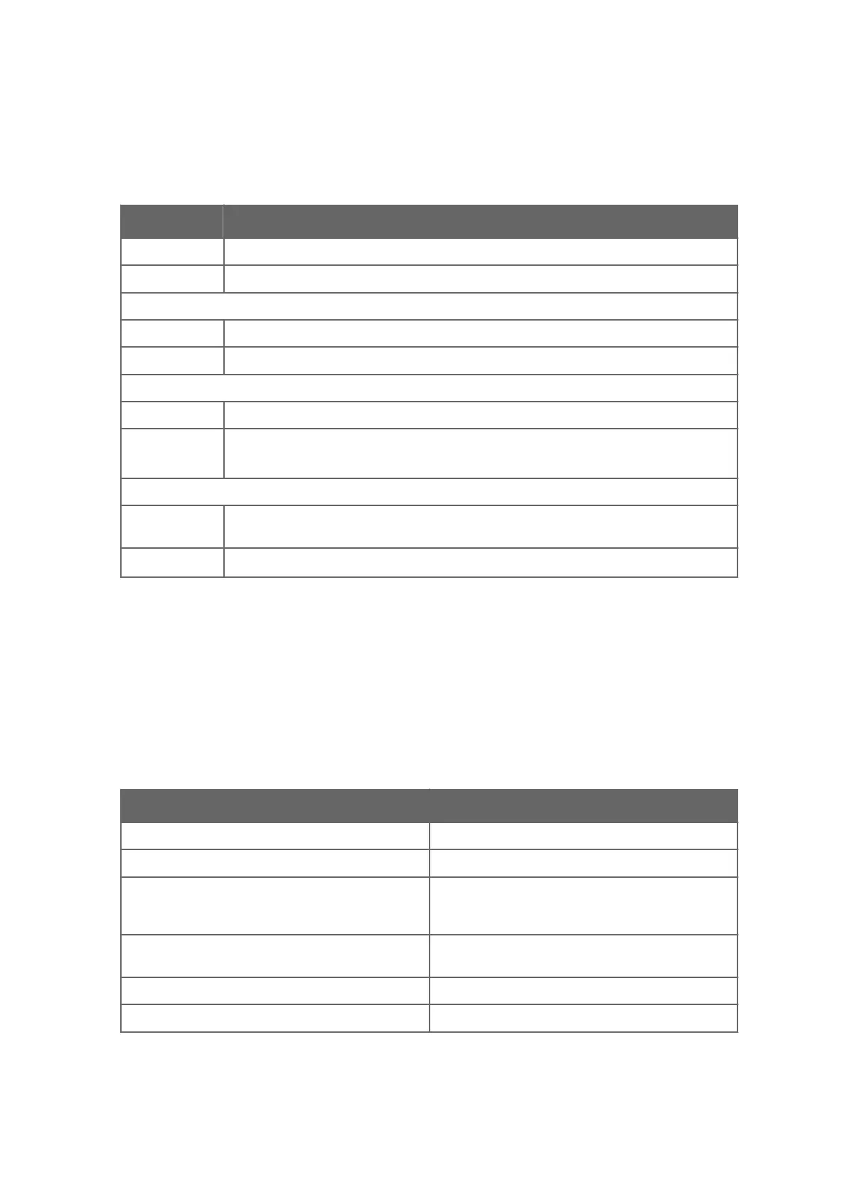
Table 58 Indicating transmitter DTR and STR model codes
Model Description
DTR Indicating transmitter (connectivity for two sensors)
STR Indicating transmitter (connectivity for one ‑IA/‑IF/‑CI sensor)
Cable connection
-U ½ in NPT type conduit hubs for CSA certified transmitter
-M M20x1.5 metric cable glands for general purpose
Electrical classification
‑GP General purpose
‑CS CSA certified for use in general purpose (ordinary) locations
Applicable to CSA and ANSI/UL standards
1)
Power supply
-AC Power supply 100‑240 V AC 50/60 Hz, fuse with voltage 250 V AC, max. size 10 A and
speed slow
-DC
Power supply 24 V DC
2)
1) Available only with cable connection code -U, ½ NPT type conduit hubs and -AC power supply.
2) With -GP option only.
13.3 Specifications
13.3.1 Indicating transmitter specifications
Table 59 Indicating transmitter specifications
Feature Specification
Display 320 x 240 pixel graphical LCD with LED backlight
Keypad 18 membrane keys
Current output Two independent current sources, 4 … 20 mA, max.
load 1000 Ω, galvanic isolation 1500 VDC or AC
(peak), hold function during prism wash
Power AC input 100-240 VAC, ±10%, 50/60 Hz / 30 VA
optional 24 VDC, Overvoltage Category II
Alarms/Wash relays Two built-in signal relays, max. 250 V/3 A
Input switches Four switch inputs
Chapter 13 – Indicating transmitter DTR and STR specifications
223

 Loading...


