Mount the indicating transmitter indoors, preferably in an easily accessible, well-lit and dry
ar
ea. Avoid vibration. Take interconnecting cable length into consideration when choosing
the mounting location.
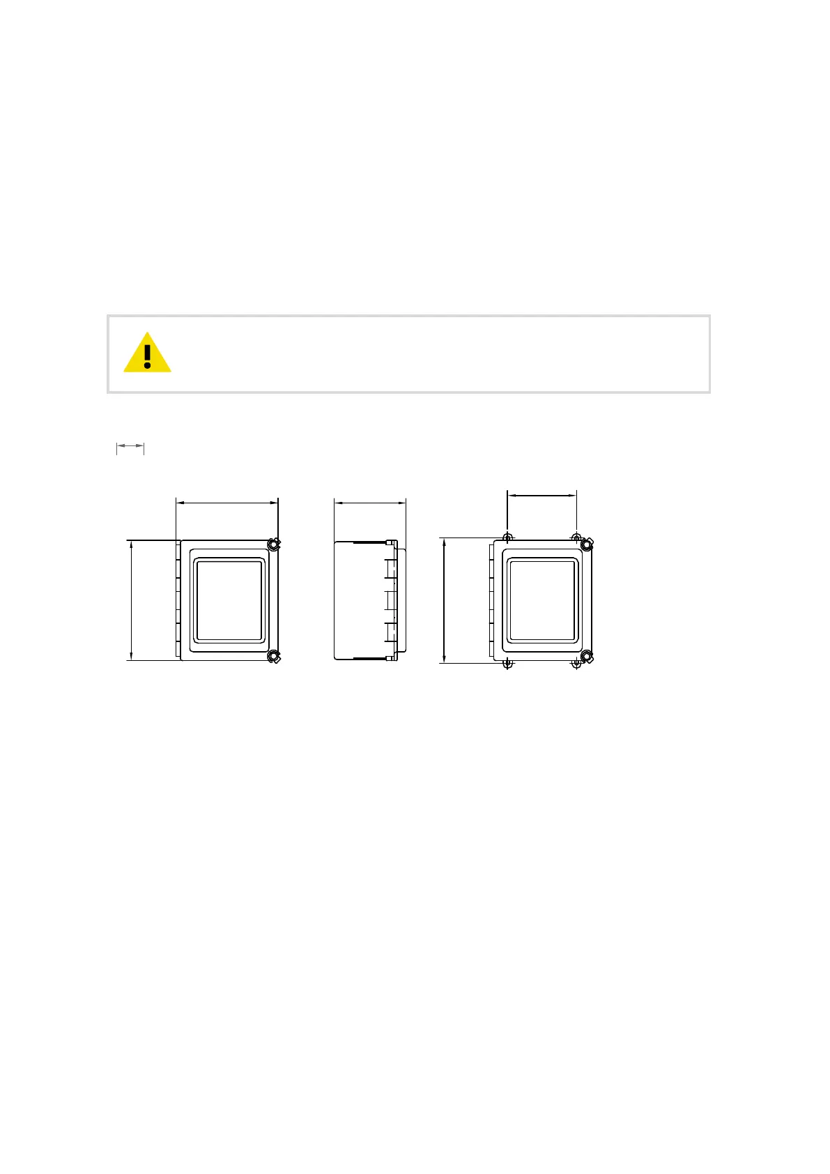
The enclosure is mounted vertically on an upright surface (wall) using four mounting feet,
see the following figure. The LCD is best viewed when approximately at the eye level of the
user.
In sanitary installations, the recommendation is to use a DTR with stainless steel enclosure. If
standard polycarbonate enclosure is used, install it as remotely as practical from product
areas or connections.
Do not drill mounting holes in the enclosure as that aec
t the protection
class of the enclosure and damage the electronics.
CAUTION!
267 [10.5]
226 [8.9] 159 [6.25]
278 [10.94]
152 [6.0]
Figure 5 Indicating transmitter dimensions and mounting feet measures
4.2 Electrical connections
4.2.1 Interconnecting cable
The cable contains a pair of twisted signal wires and a cable shield, see
Figure 9 (page 31).
Standard delivery is 10 m (33 ft) of cable. The maximum length of an interconnecting cable
is 200 m (660 ft). The signal wires are interchangeable (non-polarized). The cable shield is
connected to the protective earth at the indicating transmitter.
The junction box enables the use of customer’s own cable as long as it meets IEC 61158-2
type A standard requirements, see Interconnecting cable specifications (page 226).
More information
‣
Connecting sensor (page 25)
PR-23 Series User Guide
IM-EN-PR23-E
24

 Loading...


