4. To set the switch function, select S
witch > 2 FUNCTION.
The current assignment of the switch is shown at the bottom of the S
witch menu
display. For example, in the previous figure, switch 1 is assigned to sensor A with
function Wash stop.
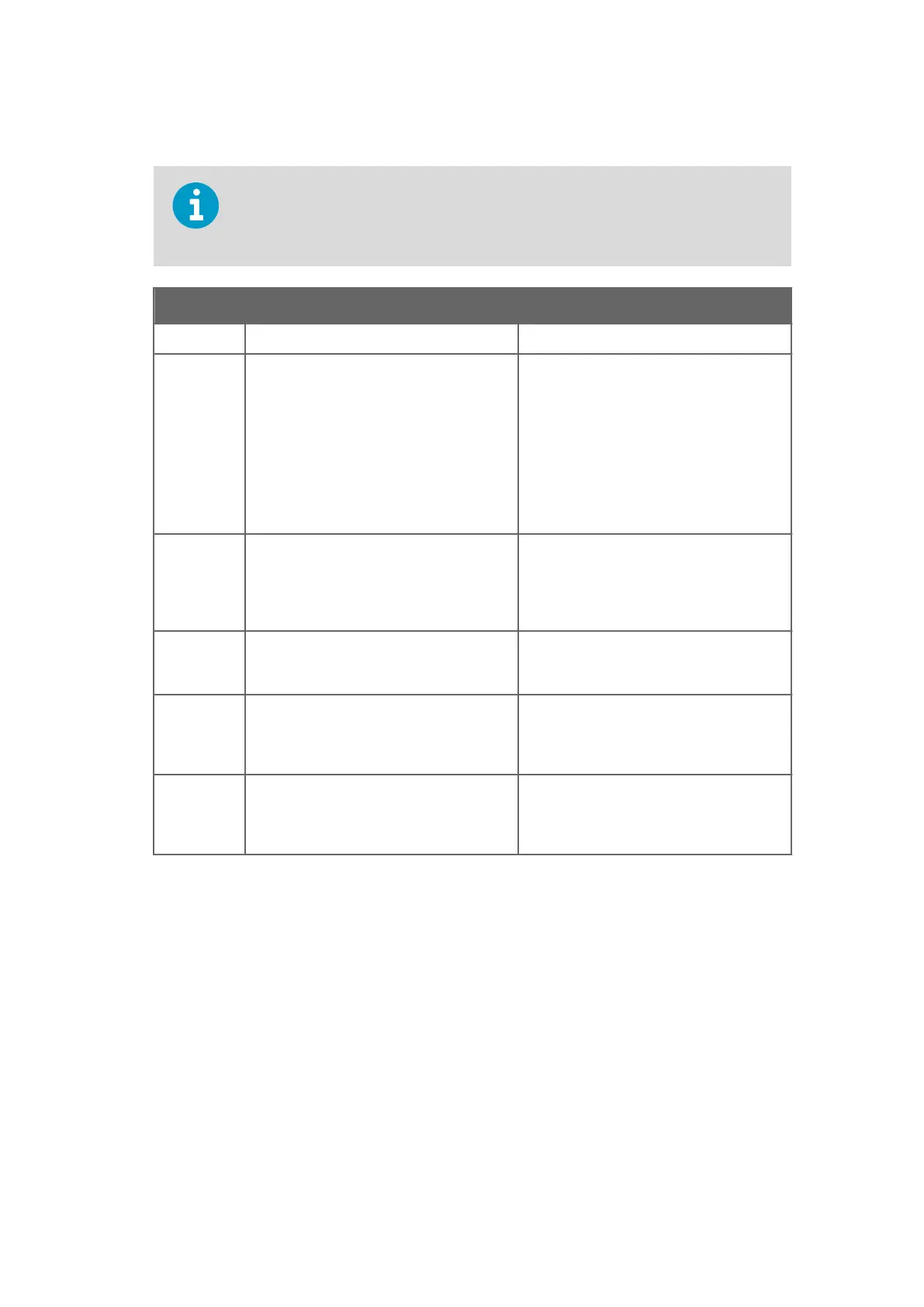
Function name Description
1 NOT DEFINED Factory setting.
2 HOLD When used with a built-in wash relay, this
func
tion is useful for an intermittent
process: the prism is washed when the
process stops (as indicated by contact
closure). The wash is repeated when the
process restarts (if the stop lasts over 60 s).
The signal is on hold between
washes.When used with an external
independent timer, contact closure holds
the output signal.
3 WASH STOP Switch closure prevents wash cycle. It can
be used t
o prevent wash action when the
process pipe is empty. The message WASH
STOP displays when a wash cycle is
initiated.
4 REMOTE WASH At switch closure the system waits for an
e
xternal wash command before initiating
wash.
5 SCALE SELECT Any chemical curve and associated field
calibr
ation scale can be selected by switch
closure. The scales assigned to each switch
independently.
6 CALIBRATION SEAL Contact closure prevents access to
calibr
ation and configuration ("external
password"). Can be used to seal the
calibration.
5. If you chose SCALE SELECT
as switch function, select Switch > 3 SCALE CHEMICAL to
enter the parameters for the chemical curve assigned to the switch. For more
information on chemical curves and chemical curve parameters, see Chemical curve
(page 74).
6. If necessary, the chemical curve assigned to a switch can be adjusted by field
calibration parameters. Select Switch > 4 SCALE FIELD to enter the parameters. For
more information on field calibration and field calibration parameters, see Field
calibration (page 75).
7.3.3 Configuring mA outputs
For the electrical properties of the two output signals, see Connecting indicating transmitter
(page 27)
.
PR-23 Series User Guide
IM-EN-PR23-E
70

 Loading...


