64 531 2 2101 1197 8
13 14
ev- ev+ ev- ev+
-vs
+vs
ISOLATOR UNIT
24VDC
Power cable
PR-8250-xxx
(max 100m)
(max 100m)
(max 100m)
Cable
PR-8230-xxx
1
2
Cable
PR-8260-xxx
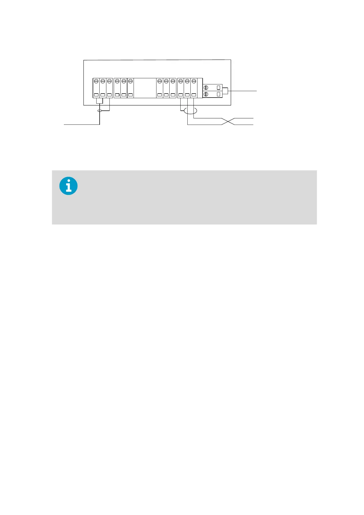
Figure 91 Isolator unit wiring
If the power to isolator unit terminals is not correctly connected, +24 VDC to terminal 14
(+vs) and zero to terminal 13 (-vs), the transmitter STR displays the message NO SIGNAL.
If terminals 11 and 12 are not correctly connected, sensor cable connecting terminal 2 of
the Indicating transmitter STR to the Isolator unit terminal 11 (-ve) and terminal 1 of the
STR to Isolator unit terminal 12 (+ve) , the message NO SIGNAL displays.
Chapter 10 – Sensor specifications
169

 Loading...


