The selection of tolerance time with DD‑23 r
equires a careful risk analysis. The use of the
tolerance time functionality does not slow down the response of the instrument when the
instrument is in Normal operation. However, it slows down the malfunction alarm in DD‑23
in case the process pipe becomes empty or some other reason makes the optical image
impossible to interpret. The recommended value for tolerance time is 5 s when a DTR is used
in a DD‑23 system.
7.3 Configuring r
efractometer system
The indicating transmitter has two built-in 4 … 20 mA outputs (mA OUTPUT 1, mA OUTPUT
2), t
wo relay contact outputs (RELAY 1, RELAY 2), and four switch inputs (SWITCH 1, SWITCH
2, SWITCH 3, SWITCH 4). Each of these resources can be freely assigned to either sensor A
or sensor B.
7.3.1 Configuring r
elays
For the electrical properties of the built-in relays, see C
onnecting indicating transmitter
(page 27). You can configure each of the two relays individually to either sensor A or sensor
B, meaning 0 … 2 relays can be assigned to a sensor. You can also open and close relays
manually, mainly to test them.
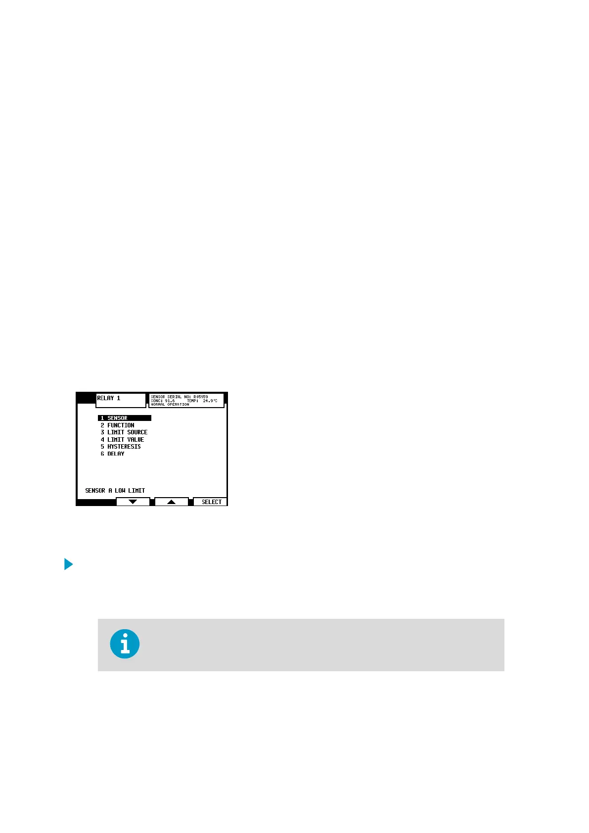
Figure 36 Relay menu for relay 1
1.
Select Menu > 5 CALIBRATION > 3 RELAYS.
2. Select the relay that you want to configure, either 1 RELAY 1 or 2 RELAY 2.
3. To assign the current relay to either sensor A or sensor B, select 1 SENSOR.
The current assignment of the relay is shown at the bottom of the R
elay menu
display. In the figure, relay 1 is assigned to sensor A with function Low limit.
PR-23 Series User Guide
IM-EN-PR23-E
66

 Loading...


