4. To set the relay function, select 2 FUNCTION.
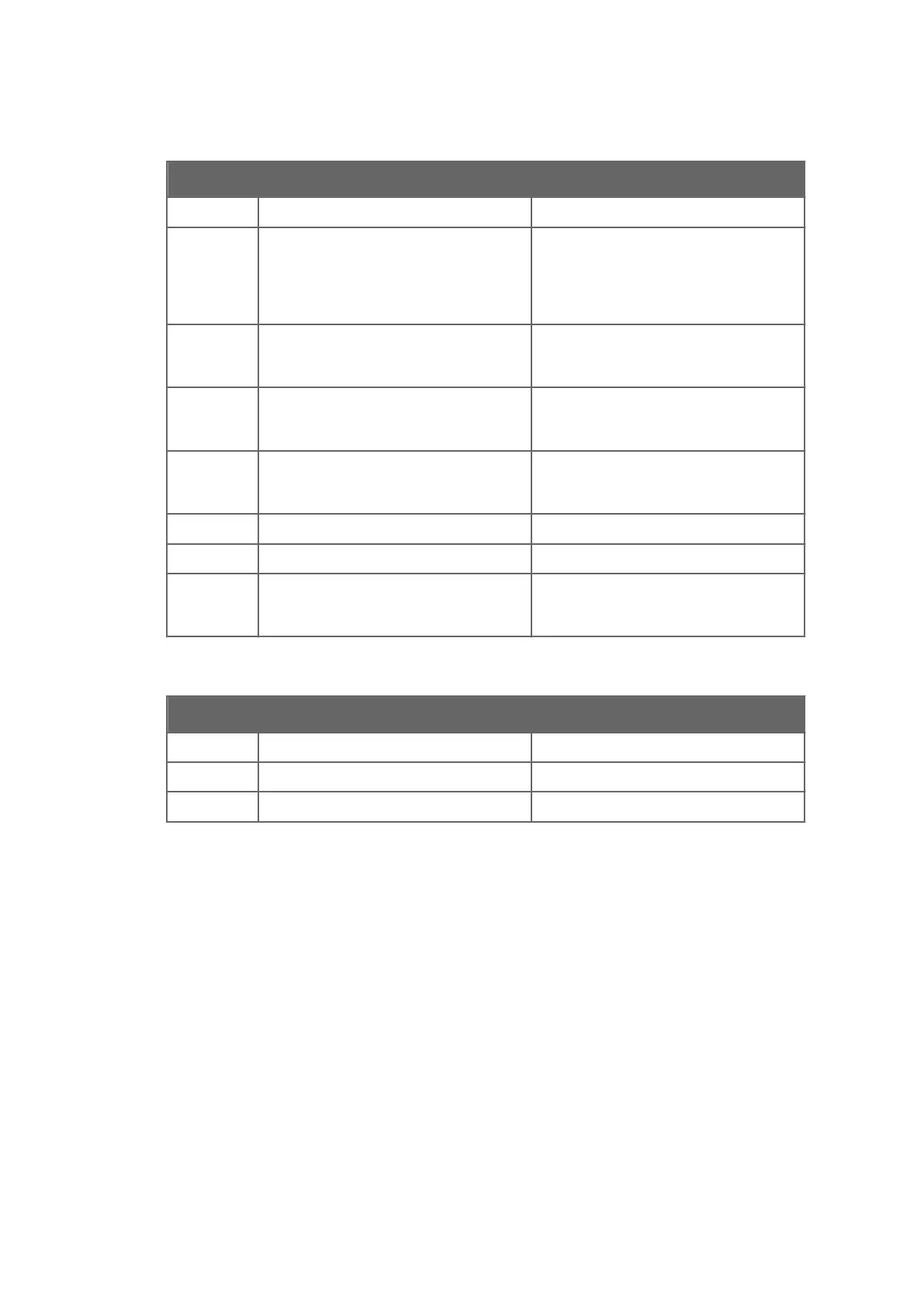
Function name Description
1 NOT DEFINED Factory setting.
2 NORMAL OPERATION Closed contact if diagnostic message is
Normal operation during HOLD, see
Configuring input switches (page 68). The
contact is also closed when message is NO
SAMPLE.
3 INSTRUMENT OK Closed contact if there is no equipment
malfunction. See also Diagnostic message
priorities (page 97).
4 LOW LIMIT Used as alarm relay, closing contact if
source value is below set limit. (See below
for limit source selection.)
5 HIGH LIMIT Used as alarm relay, closing contact if
source value is above set limit. (See below
limit source selection.)
6 PRECONDITION See Wash cycle (page 77).
7 WASH See Configuring prism wash (page 77).
8 PRISM WASH FAILURE Closed contact if diagnostic message is
PRISM WASH FAILURE, see Setting prism
wash parameters (page 82).
5. If you choose either low limit or high limit as relay function, you must define a limit
source. To set the limit source, select Relay > 3 LIMIT SOURCE. Limit source selection:
Function name
Description
1 NOT DEFINED Factory setting.
2 CONCENTRATION Measured concentration CONC
3 PROCESS TEMPERATURE Process temperature
6. To set the limit value select Relay > 4 LIMIT VALUE, and enter a numeral limit value.
7. To set the hysteresis value select Relay > 5 HYSTERESIS. The hysteresis value indicates
how soon the relay opens after the process has temporarily gone over the high limit or
under the low limit. For example, if high limit is 50 and hysteresis is 2, the relay opens
only once the process drops to below 48.
8. To change the relay delay time, select Relay > 6 DELAY. The delay is given in seconds,
factory setting is 10 s.
Chapter 7 – Configuration and calibration
67

 Loading...


