List of figures
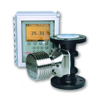
Figure 1 Refractometer equipment.............................................................................13
Figure 2 Sensor structure...............................................................................................16
Figure 3 Indicating transmitter enclosure..................................................................21
Figure 4 Linearized curve.............................................................................................. 22
Figure 5 Indicating transmitter dimensions and mounting feet measures..... 24
Figure 6 Sensor electrical connections......................................................................26
Figure 7 Opening indicating transmitter front panel.............................................29
Figure 8 External power switch...................................................................................30
Figure 9 Motherboard (AC power).............................................................................. 31
Figure 10 Motherboard (24 VDC)..................................................................................32
Figure 11 Location of reset button............................................................................... 36
Figure 12 Prism wash system for steam (non-sanitary)......................................... 39
Figure 13 Sanitary prism wash system for steam.....................................................40
Figure 14 Pressure reducing valve PR‑3341‑J............................................................. 41
Figure 15 Install strainer horizontally...........................................................................42
Figure 16 Wiring for a prism wash system for steam.............................................. 43
Figure 17 Prism wash system for high pressure water............................................44
Figure 18 Wiring for prism wash system for high pressure water....................... 45
Figure 19 Wash nozzles for flow cell AFC‑HSS‑XXX‑XX‑NC................................. 46
Figure 20 Process connection of wash nozzle in flow cell......................................47
Figure 21 Mounting of wash nozzle for sanitary probe
refractometer PR‑23
‑AP............................................................................... 48
Figure 22 Mounting of wash nozzle for process refractometer PR‑23‑GP........ 49
Figure 23 Main display alternatives.............................................................................. 50
Figure 24 DTR keyboard and Main menu for sensor B............................................ 52
Figure 25 Display setup menu........................................................................................53
Figure 26 Main display format selection..................................................................... 54
Figure 27 System description.........................................................................................55
Figure 28 Optical images with IDS................................................................................56
Figure 29 Slope graph with IDS..................................................................................... 56
Figure 30 Optical images with VD.................................................................................57
Figure 31 Exponential damping.................................................................................... 60
Figure 32 Linear damping................................................................................................ 61
Figure 33 Slew rate damping..........................................................................................62
Figure 34 Eect of tolerance time on output............................................................ 64
Figure 35 Damping stops during hold......................................................................... 65
Figure 36 Relay menu for relay 1....................................................................................66
Figure 37 Output menu for mA Output 1......................................................................71
Figure 38 Default mA output values.............................................................................72
Figure 39 Concentration calibration layers................................................................. 73
Figure 40 Using FIELD SAMPLE soft key.....................................................................76
Figure 41 Automatic prism wash cycle........................................................................77
Figure 42 Wash logic.........................................................................................................79
Figure 43 Wash cycle......................................................................................................... 81
Figure 44 Transmitter card positions............................................................................86
Figure 45 Motherboard PR‑10600 and H1 interface card PR‑10701..................... 87
Figure 46 Troubleshooting blank display....................................................................88
Figure 47 Checking power supply.................................................................................89
Figure 48 Diagnostic LED functions.............................................................................. 91
Figure 49 Sensor nameplates.........................................................................................99
Figure 50 PR‑23 rangeability........................................................................................100
PR-23 Series User Guide
IM-EN-PR23-E
6
 Loading...

