To set the communication address for intelligent locks on IT cabinets:
The address setting can be done through the intelligent lock debugging program or the web UI of the Vertiv™ Liebert®
RDU501 Intelligent Monitoring Unit. The following table shows the DIP switch numbers (on the back of the lock) and the
corresponding communication addresses.
DIP Switch Number Communication Address
1 1
2 2
3 4
4 8
5 16
Table 7.4 Intelligent Lock DIP Switch Communication Address
The following figure describes the setup of the intelligent door lock IDs.
Product
Cabinet Front Door
Smart Lock Address
Connect to Intelligent
Monitoring Unit
Cabinet Rear Door
Smart Lock Address
Connect to Intelligent
Monitoring Unit
CRV cooling
system 1
10
8COM Card/COM 1
10
8COM Card/COM 2
PMC 9 9
IT rack cabinet 1 1 1
IT rack cabinet 2 2 2
IT rack cabinet 3 3 3
CRV cooling
system 2
11 11
Cabinet 4 4
8COM Card/COM 3
5
8COM Card/COM 4
Cabinet 5 5 6
Table 7.5 Intelligent Lock ID Settings
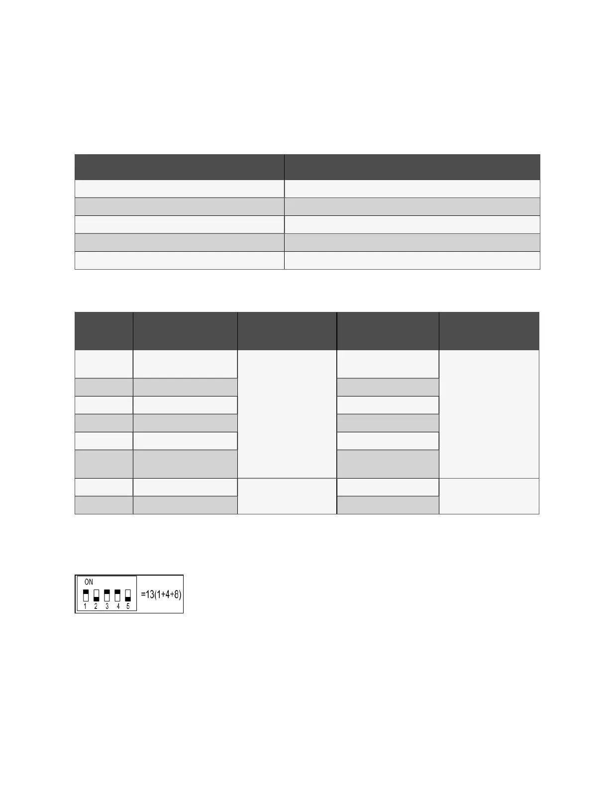
Address Example
Figure 7.4 Intelligent Lock Address Number
Explanation
Since the numbers 1, 3, and 4 are ON, refer to Intelligent Lock DIP Switch Communication Address above to determine the
communication addresses associated with each of those three numbers. The communication addresses are 1, 4, and 8. To
determine the communication address, add those three values (1+4+8) together. The communication address for the
intelligent door lock is 13.
54 Proprietary and Confidential ©2024 Vertiv Group Corp. 7 Network Settings
Vertiv™ SmartRow™ 2 Infrastructure Solution User Guide