242 Run-time System CODESYS 2.3 WAGO-I/O-SYSTEM 750
750-8208 PFC200 CS 2ETH RS CAN DPM
Manual
Version 1.1.0, valid from FW Version 02.06.20(09)
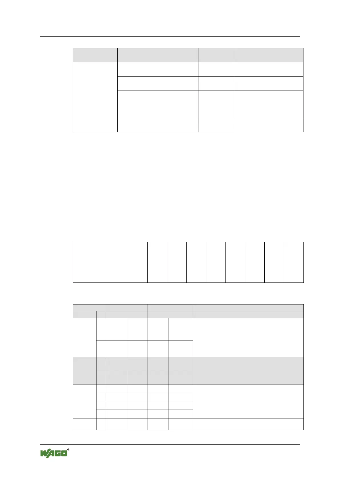
Table 188: Access to the Process Images of the Input and Output Data – Flags
Total of 128 kB remanent
memory (65536 words).
104 kB addressed by word via
MODBUS (53248 words)
Word (MODBUS)
%MW0 to %MW3327
6.5 kB addressed by bit via
MODBUS (3328 words).
Write
%MX0.0 … %MX0.15 to
%MX3327.0 …
Retain memory addressed by
symbols in the NVRAM: 128 kB
* The use of up to 250 I/O modules is possible with the WAGO internal data bus extension
modules.
The total size of the memory for flag and retain variables is 128 kB (131060
bytes). The size of these two sections can be customized as required, provided the
total (permissible) size is not exceeded.
If you are using bit-oriented addressing, remember that the basic address is word-
based. The bits are addressed from 0 to 15.
8.8 Addressing Example
The following addressing example clarifies the access to the process image:
Table 189: Arrangement of the I/O Modules for the Addressing Example
400
554
402
504
454
650
468
600
Table 190: Addressing Example
750-400
1
%IX8.0
1. Digital input module with a data width of 2
bits. As the analog input modules already
occupy the first 8 words of the input process
image, the 2 bits occupy the lowest-value bits
2
%IX8.1
750-554
1
%QW0
1. Analog output module with a data width of
2 words. This module occupies the first 2
words in the output process image.
2
%QW1
750-402
%IX8.2
2. Digital input module with a data width of 4
bits. These are added to the 2 bits of the 750-
400 module and stored in the 8th word of the
input process image.
2
%IX8.3
3
%IX8.4
4
%IX8.5
750-504
1
%QX4.0

 Loading...