404 Appendix WAGO-I/O-SYSTEM 750
750-8208 PFC200 CS 2ETH RS CAN DPM
Manual
Version 1.1.0, valid from FW Version 02.06.20(09)
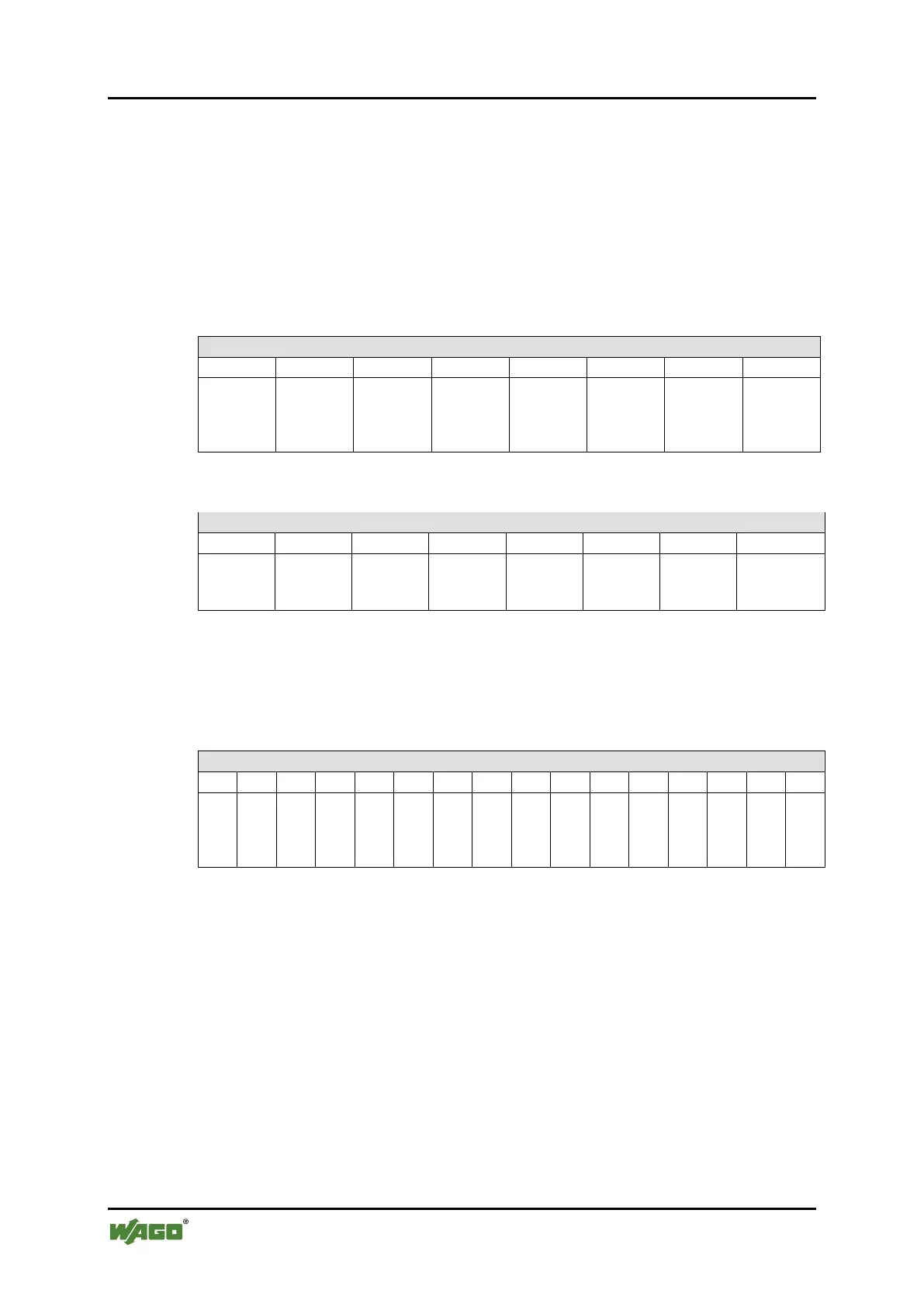
15.1.2.7 8 Channel Digital Output Modules with Diagnostics and Input
Process Data
750-537
The digital output modules have a diagnostic bit for each output channel. When an
output fault condition occurs (i.e., overload, short circuit, or broken wire), a
diagnostic bit is set. The diagnostic data is mapped into the Input Process Image,
while the output control bits are in the Output Process Image.
Table 275: 8 Channel Digital Output Modules with Diagnostics and Input Process Data
bit
S 8
bit
S 7
bit
S 6
bit
S 5
bit
S 4
bit
S 3
bit
S 2
bit
S 1
Diagnostic bit S = ‘0’ no Error
Diagnostic bit S = ‘1’ overload, short circuit, or broken wire
DO 8
DO 7
DO 6
DO 5
DO 4
DO 3
DO 2
DO 1
15.1.2.8 16 Channel Digital Output Modules
750-1500, -1501, -1504, -1505
Table 276: 16 Channel Digital Output Modules
DO 16
16
s
DO 15
s DO
14
s
DO 13
s
DO 12
s
DO 11
DO 10
10
s
DO 9
s
DO 8
s
DO 7
s
DO 6
s
DO 5
s
DO 4
s
DO 3
s
DO 2
s
DO 1

 Loading...