WAGO-I/O-SYSTEM 750 PROFIBUS DP-V1 Master 341
750-8208 PFC200 CS 2ETH RS CAN DPM
Manual
Version 1.1.0, valid from FW Version 02.06.20(09)
5. Click [Delete] to delete any I/O modules you may have added in error.
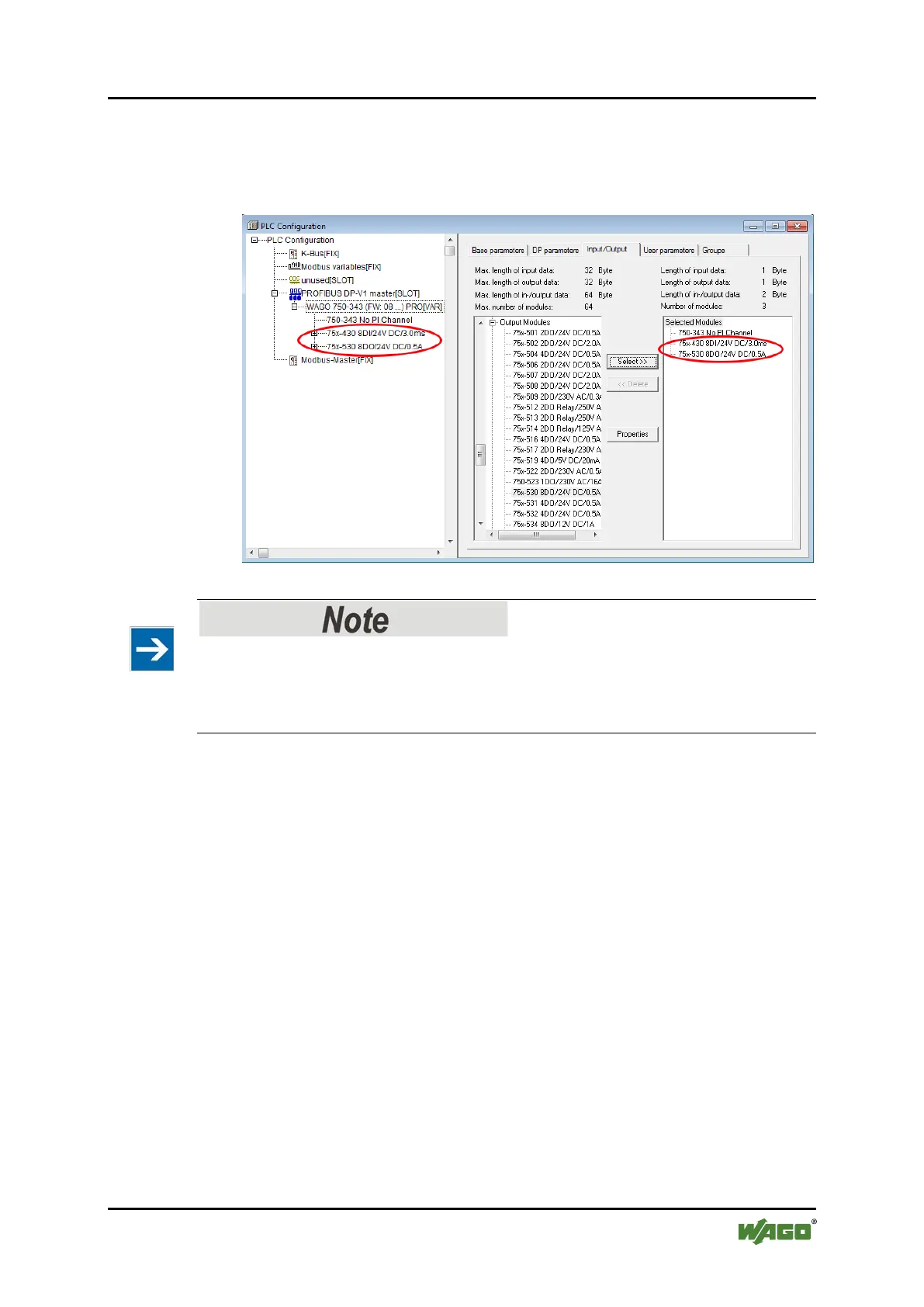
The example below shows a digital input module (750-430) and a digital
output module (750-530) connected to the slave.
Figure 146: Selecting I/O modules
I/O modules without process data are not considered.
I/O modules that do not provide any process data (e.g., power supply module, end
module) are not taken into consideration in the configuration and therefore do not
appear in the GSD file selection list.
To optimize the address memory, there are also the digital 2-channel and 4-
channel I/O modules in the configuration “*750-xxx”. When using these
marked I/O modules, the slave fills a byte (8 bit) previously started with
“750-xxx” with the process data from the current I/O module.

 Loading...