WAGO-I/O-SYSTEM 750 Appendix 409
750-8208 PFC200 CS 2ETH RS CAN DPM
Manual
Version 1.1.0, valid from FW Version 02.06.20(09)
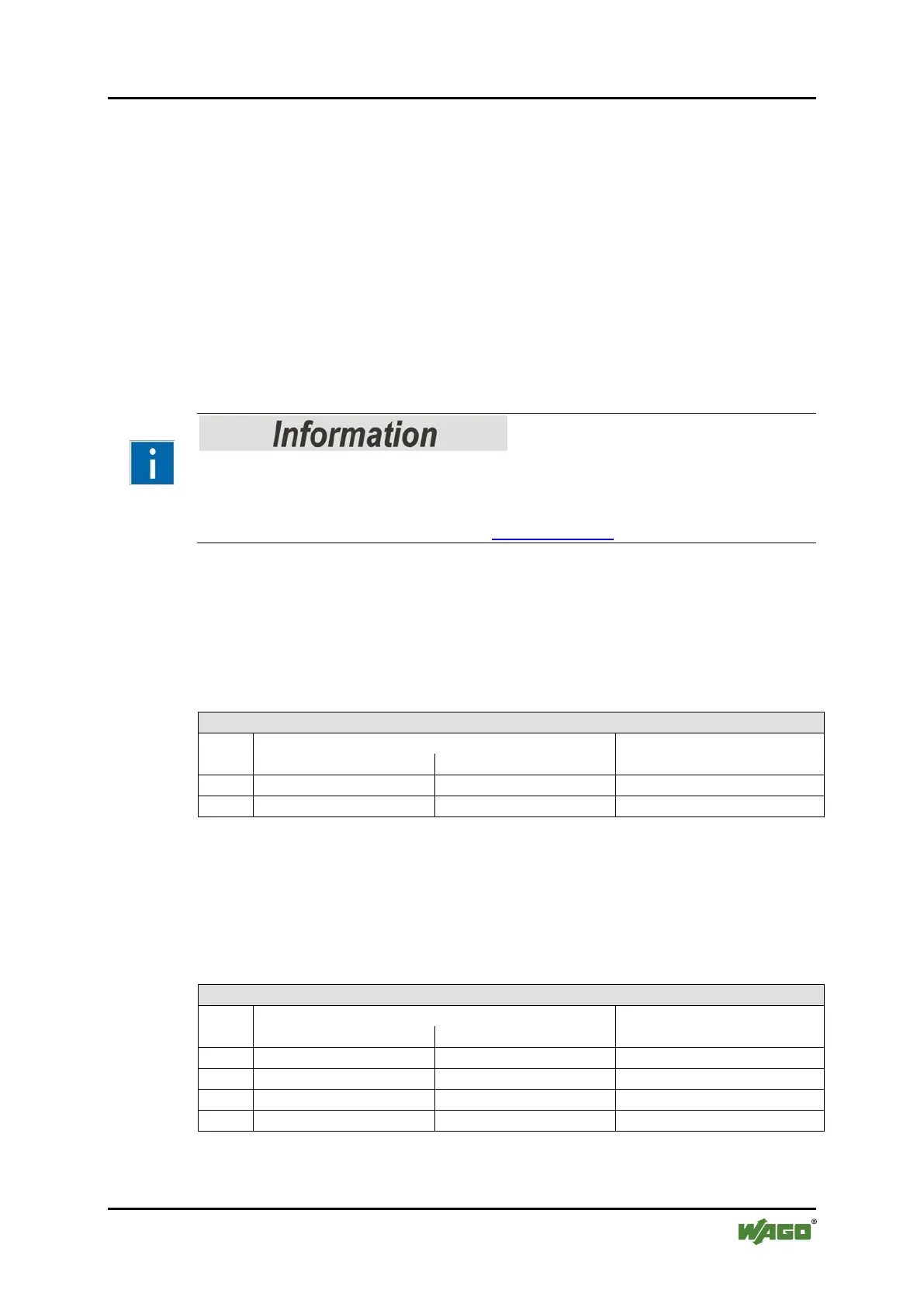
15.1.4 Analog Output Modules
The analog output modules provide 16-bit output values and 8 control/status bits
per channel.
The controller only uses the 8 control/status bits internally for
configuration/parameterization (e.g., via WAGO-I/O-CHECK).
Therefore, only the 16-bit measurement values for each channel are in Intel
format and are mapped by word in the output process image for the controller.
When digital output modules are also present in the node, the analog output data
is always mapped into the Output Process Image in front of the digital data.
Information on the structure of control and status bytes
For detailed information on the structure of a particular I/O module’s
control/status bytes, please refer to that module’s manual. Manuals for each
module can be found on the Internet at www.wago.com.
15.1.4.1 2 Channel Analog Output Modules
750-550, -552, -554, -556, -560, -562, 563, -585, (and all variations),
753-550, -552, -554, -556
Table 283: 2 Channel Analog Output Modules
Offset
Description
15.1.4.2 4 Channel Analog Output Modules
750-553, -555, -557, -559,
753-553, -555, -557, -559
Table 284: 4 Channel Analog Output Modules
Offset
Description

 Loading...