WAGO-I/O-SYSTEM 750 Appendix 413
750-8208 PFC200 CS 2ETH RS CAN DPM
Manual
Version 1.1.0, valid from FW Version 02.06.20(09)
15.1.5.4 Serial Interface Modules with Standard Data Format
750-650/000-001, -014, -015, -016
750-653/000-001, -006
The above Serial Interface Modules with Standard Data Format have a total of 6
bytes of user data in both the Input and Output Process Image (5 bytes of serial
data and 1 byte of control/status). The following table illustrates the Input and
Output Process Image, which have a total of 3 words mapped into each image.
Word alignment is applied.
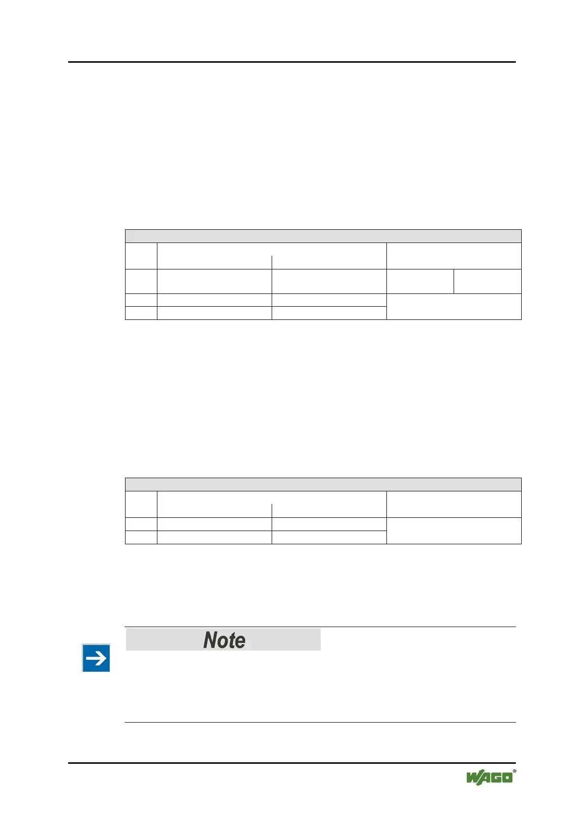
Table 290: Serial Interface Modules with Standard Data Format
Input and Output Process Image
Offset
Description
0 D0 C/S Data byte
Data bytes
15.1.5.5 Data Exchange Module
750-654, (and the variation /000-001)
The Data Exchange modules have a total of 4 bytes of user data in both the Input
and Output Process Image. The following tables illustrate the Input and Output
Process Image, which has a total of 2 words mapped into each image.
Word alignment is applied.
Table 291: Data Exchange Module
Input and Output Process Image
Offset
Description
Data bytes
15.1.5.6 SSI Transmitter Interface Modules
750-630 (and all variations)
The process image of the / 003-000-variants depends on the parameterized
operating mode!
The operating mode of the configurable /003-000 I/O module versions can be set.
Based on the operating mode, the process image of these I/O modules is then the
same as that of the respective version.

 Loading...