WAGO-I/O-SYSTEM 750 Run-time System CODESYS 2.3 243
750-8208 PFC200 CS 2ETH RS CAN DPM
Manual
Version 1.1.0, valid from FW Version 02.06.20(09)
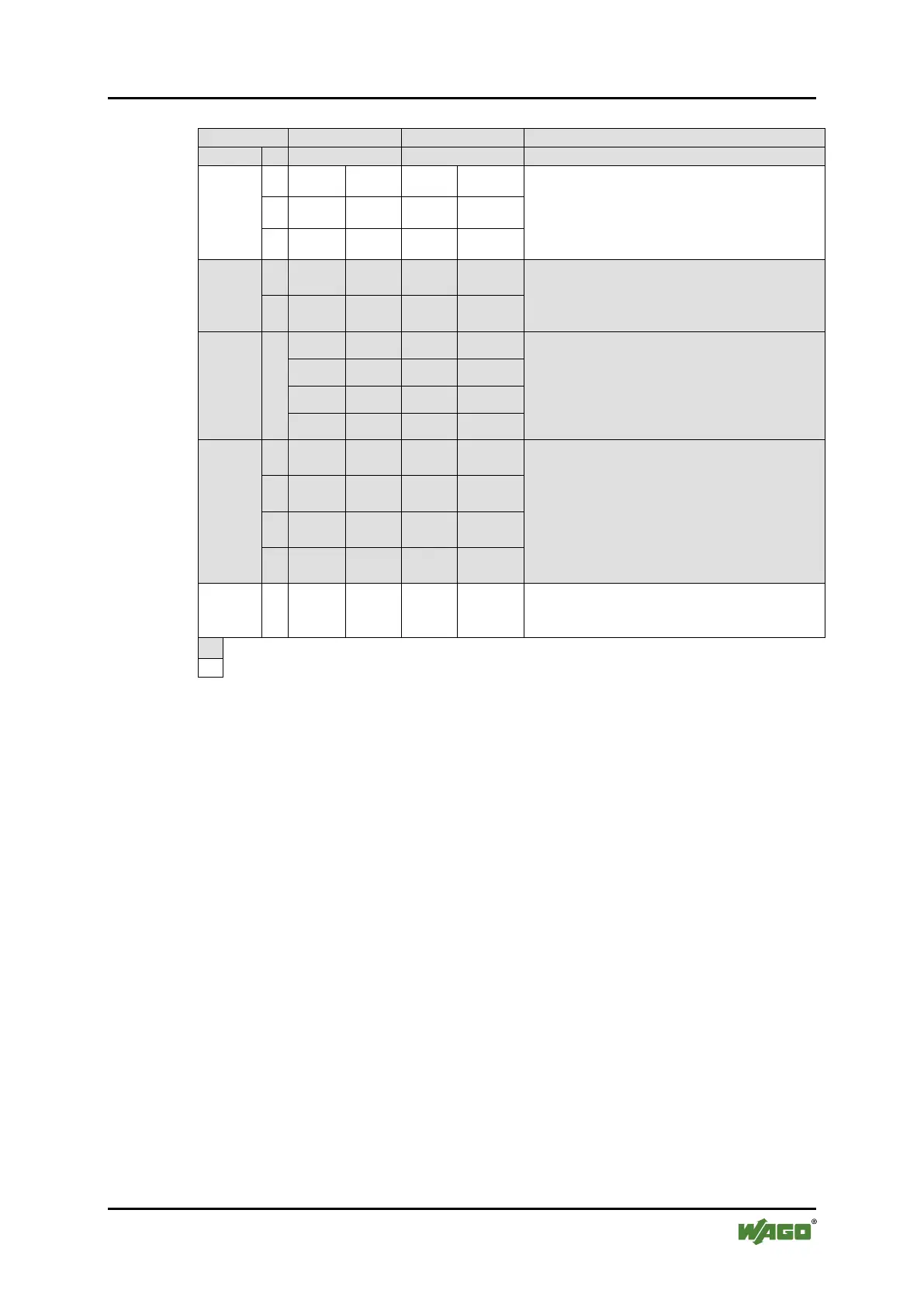
Table 190: Addressing Example
2
%QX4.1
1. Digital output module with a data width of
4 bits. As the analog output module already
occupies the first 4 words of the output
process image, the 4 bits occupy the lowest-
value bits of the 4th word.
3
%QX4.2
4
%QX4.3
750-454
1
%IW0
1. Analog input module with a data width of 2
words. This module occupies the first 2 words
in the input process image.
2
%IW1
750-650
1
%IW2
RS-232, C 9600/8/N/1:
The serial interface module is an analog input
and output module, which displays 2 words
both in the input process image and in the
output process image.
%IW3
%QW2
%QW3
750-468
1
%IW4
4AI, 0 – 10 V S.E:
2. Analog input module with a data width of 4
words. As the 750-454 and 750-650 analog
input and output modules already occupy the
first 4 words of the input process image, the 4
words of this I/O module are added behind the
others.
2
%IW5
3
%IW6
4
%IW7
750-600
The passive 750-600 end module does not
Analog input and output modules
Digital input and output modules
*
C: Number of the input/output
8.9 Internal Data Bus Synchronization
The internal data bus cycle and the CODESYS task cycle are optimally
automatically synchronized: This depends on the number of I/O modules
connected and the fastest CODESYS task cycle set in the fieldbus controller. The
synchronization cases described below can therefore take place.
In this chapter, CODESYS task denotes only tasks within CODESYS that contain
an access to the internal data bus. Tasks that do not access the internal data bus
are not synchronized in the same way as described below. For this, see Section
“Creating Tasks.”
8.9.1 Case 1: CODESYS Task Interval Set Smaller than the I/O
Module Cycle
Execution of the CODESYS tasks is synchronized with internal data bus cycle
time.
The CODESYS task is processed in parallel to the internal data bus cycle. The
CODESYS task interval is extended to the internal data bus cycle time. This is
necessary so that each CODESYS task is started with new input data from the

 Loading...