WAGO-I/O-SYSTEM 750 Table of Contents 3
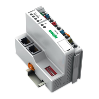
750-8208 PFC200 CS 2ETH RS CAN DPM
Manual
Version 1.1.0, valid from FW Version 02.06.20(09)
Table of Contents
1 Notes about this Documentation ............................................................... 15
1.1 Validity of this Documentation ............................................................... 15
1.2 Copyright ................................................................................................. 15
1.3 Symbols ................................................................................................... 16
1.4 Number Notation ..................................................................................... 18
1.5 Font Conventions .................................................................................... 18
2 Important Notes ......................................................................................... 19
2.1 Legal Bases ............................................................................................. 19
2.1.1 Subject to Changes ............................................................................. 19
2.1.2 Personnel Qualifications ..................................................................... 19
2.1.3 Use of the WAGO-I/O-SYSTEM 750 in Compliance with Underlying
Provisions ........................................................................................... 19
2.1.4 Technical Condition of Specified Devices ......................................... 20
2.2 Safety Advice (Precautions) .................................................................... 21
2.3 Licensing Terms of the Software Package Used ..................................... 23
2.4 Special Use Conditions for ETHERNET Devices .................................. 23
3 Device Description ..................................................................................... 24
3.1 View ........................................................................................................ 27
3.2 Labeling ................................................................................................... 29
3.2.1 Manufacturing Number ...................................................................... 29
3.3 Connectors ............................................................................................... 30
3.3.1 Data Contacts/Internal Bus ................................................................. 30
3.3.2 Power Jumper Contacts/Field Supply ................................................ 31
3.3.3 CAGE CLAMP
®
Connectors ............................................................. 32
3.3.4 Service Interface ................................................................................. 33
3.3.5 Network Connections – X1, X2 ......................................................... 34
3.3.6 RS-232/RS-485 – X3 Communication Connection ........................... 35
3.3.6.1 Operating as an RS-232 Interface .................................................. 36
3.3.6.2 Operating as an RS-485 Interface .................................................. 37
3.3.7 CANopen – X4 Fieldbus Connection ................................................. 38
3.3.8 PROFIBUS DP – X5 Fieldbus Connection ........................................ 40
3.4 Display Elements .................................................................................... 42
3.4.1 Power Supply Indicating Elements .................................................... 42
3.4.2 Fieldbus/System Indicating Elements ................................................ 43
3.4.3 Memory Card Indicating Elements .................................................... 44
3.4.4 Network Indicating Elements ............................................................. 45
3.5 Operating Elements ................................................................................. 46
3.5.1 Operating Mode Switch ...................................................................... 46
3.5.2 Reset Button ....................................................................................... 47
3.6 Slot for Memory Card ............................................................................. 48
3.7 Schematic Diagram ................................................................................. 49
3.8 Technical Data ........................................................................................ 50
3.8.1 Device Data ........................................................................................ 50
3.8.2 System Data ........................................................................................ 50
3.8.3 Power supply ...................................................................................... 50
3.8.4 Clock................................................................................................... 51

 Loading...