372 PROFIBUS DP-V1 Master WAGO-I/O-SYSTEM 750
750-8208 PFC200 CS 2ETH RS CAN DPM
Manual
Version 1.1.0, valid from FW Version 02.06.20(09)
11.3.7.2 Description of Diagnostic Information for WAGO I/O Modules
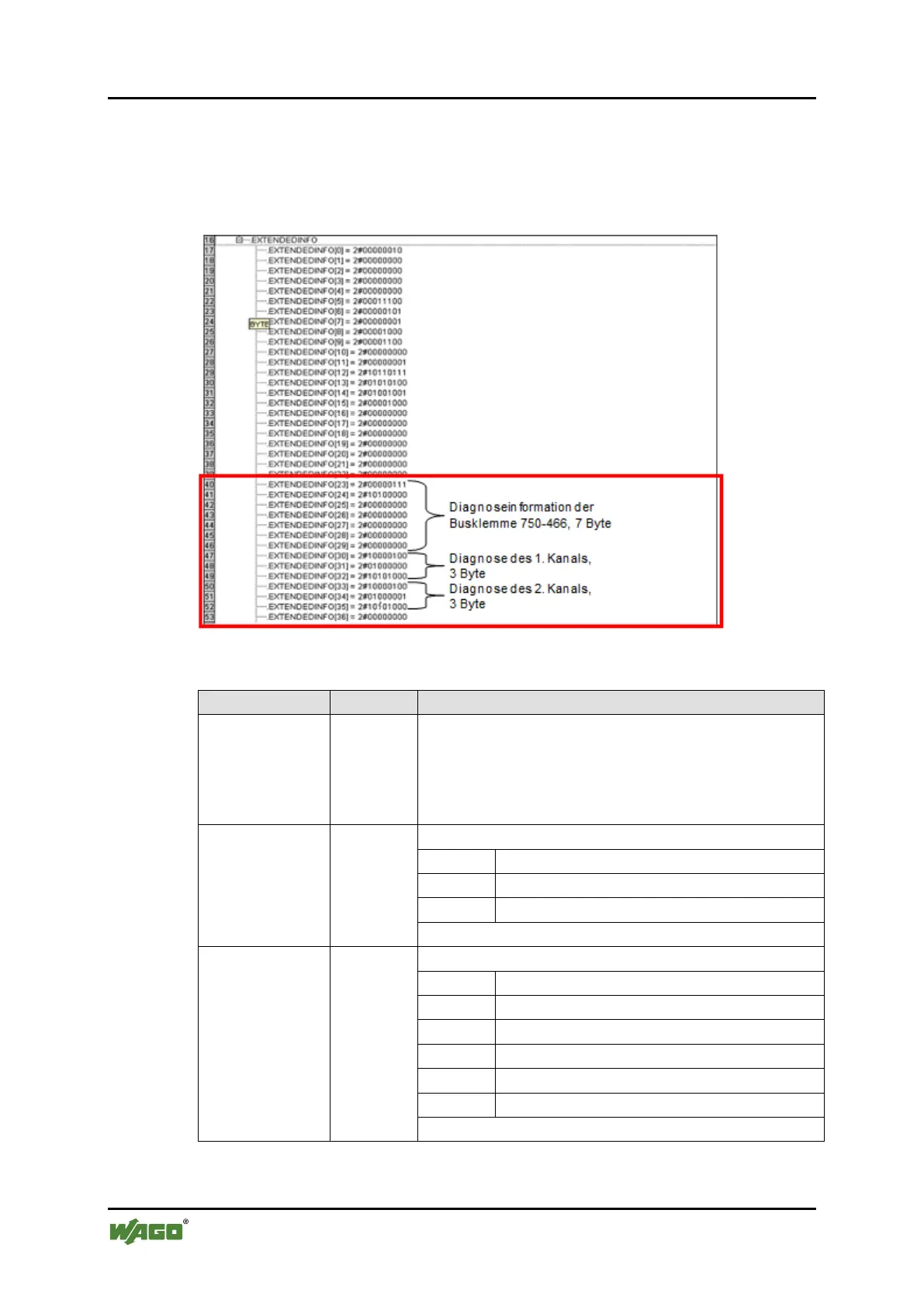
The WAGO I/O module diagnostic information is stored beginning with array
element EXTENDEDINFO[23]. Decoding of the diagnostic information is shown
here using the dual channel, 750-466 input module as an example.
Figure 173: Online view of the EXTENDEDINFO array in binary representation (1)
Table 240: Channel 1 of the 750-466 Input Module
Slot for input module; in this case the third (slot 4).
Note:
The first slot is reserved for the fieldbus coupler and
controller including the supply module. Therefore,
the first I/O module is inserted in the second slot.
The first two bits indicate the type of channel:
The other bits indicate the channel number.
The first three bits indicate the type of channel:
The other bits indicate I/O module errors.

 Loading...