Watlow F4T • 133 • Chapter 5 Function Reference
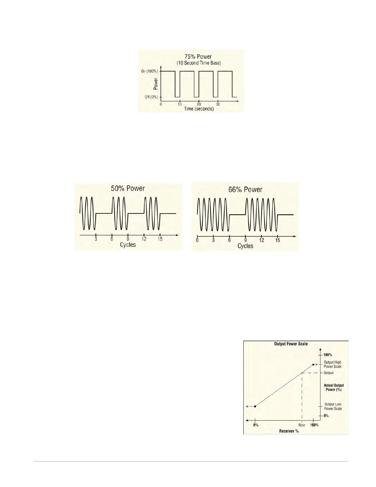
Time Base. For example, if the Fixed Time Base is ten seconds and 75% power is called
for, the output turns on for 7.5 seconds and off for 2.5 seconds, and repeats as illus-
trated below. This is appropriate for mechanical relays.
• Variable Time Base: the output switches as often as every three ac line cycles. For
example, when 66% power is called for, the output is on for six ac cycles and off for
three, and when 50% power is called for, the output is on for three ac cycles and off
for three. This method is appropriate for Solid-State Relays (SSR) or Silicon Controlled
Rectifier (SCR) power controllers. Do not use a variable time base output to control
electromechanical relays, mercury displacement relays, inductive loads or heaters with
unusual resistance characteristics.
Fixed Time Base
Set the duration of one on-off cycle. This applies when the Time Base Type is set to Fixed
Time Base.
Range: 0.1 to 60.0 seconds
Low Power Scale
Set the minimum power level for the output. When the input equals 0% (off), the output is
equal to the value set here. When the input equals 100% (on), the output is equal to the value
set with High Power Scale. Values between 0% and 100% are scaled proportionally. See the il-
lustration to the right.
Range: 0.0 to 100.0%
High Power Scale
Set the maximum power level for the output. When the input
equals 100% (on), the output is equal to the value set here.
When the input equals 0% (off), the output is equal to the
value set with Output Low Power Scale. Values between 0%
and 100% are scaled proportionally. See the illustration to the
right.
Range: 0.0 to 100.0%