Watlow F4T • 187 • Chapter 5 Function Reference
Special Output
Use this block to operate outputs for one of these applications: operating mechanical com-
pressors, controlling a motorized valve or sequencing multiple output devices to switch large
power loads. This FB is found in the Function Block Diagram editor’s Library. Within the Li-
brary, the number of these blocks available is shown in parenthesis and that number is deter-
mined by the controller part number.
Choose the algorithm with the Function parameter. These options for the Function parameter
are described in detail in the following sections:
Off: the first output follows the input all others are off.
Compressor Control: operates a compressor to meet demands for cooling or dehumidification
from one or two control loops while protecting it from excessive cycling.
Sequencer: operates a proportional power control and up to three on-off power controls as if
they were a single, larger, proportional controller.
Motorized Valve: operates a proportional valve without position feedback.
Off
The first output follows the input, all others are off.
Compressor Control
This function coordinates the demands of one or two control loops for a single compressor
and eliminates short cycling of the compressor. For example, when a compressor is used for
controlling an environment, a control loop may adjust a bypass valve proportionally to the
amount of cooling needed and another loop may adjust a valve proportionally for dehumidi-
fication. Both require the compressor to be on, but to save power and extend the life of the
compressor, it is desirable for the compressor to be off when it is not needed. The output
from this function turns the compressor on in anticipation of its use by either loop and turns
it off when it is not needed. The need for the compressor is anticipated by monitoring the
power outputs from the two loops (Input A for one loop and Input B for the second loop, if
used).
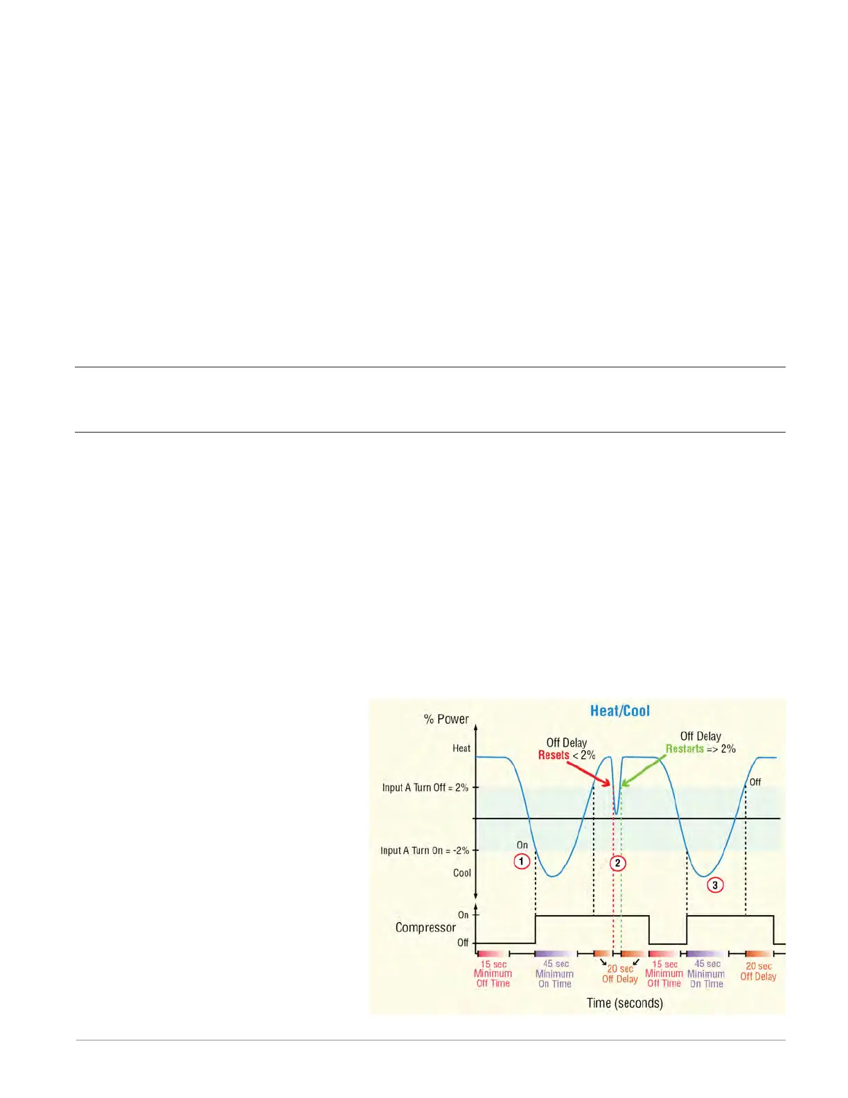
The diagram below illustrates how the compressor control functions for a single heat/cool
loop.
Compressor Settings:
Input A Turn On = -2%
Input A Turn Off = 2%
Minimum Off Time = 15 (sec)
Minimum On Time = 45 (sec)
Off Delay = 20 (sec)
Compressor Operation (Graphic Ex-
plained):
① In this example, the power signal
from the temperature loop is con-
nected to Input A of the FB. When
the power signal drops below its
Turn On setting (-2%) and the Mini-
mum Off Time (15 sec) has been