Watlow F4T • 93 • Chapter 5 Function Reference
Deviation
Deviation may be used instead of Process when it is desirable for the output range to be de-
fined relative to a value that might change frequently or automatically. For cascade control,
the outer loop will compare the outer process variable (PVO) to its set point. Based on the
result of the comparison (error), the outer loop will generate a power level. This power level
will be converted and scaled as an adjustment to the inner loop set point.
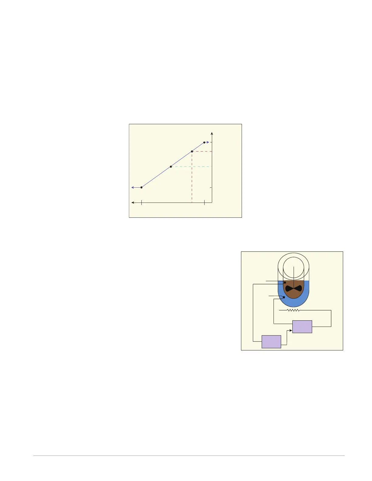
In the graphic below, the solid line illustrates the proportional relationship between the scal-
ing factors and the user defined range adjustment (-10 to +10) with the resultant inner loop
set point (dashed lines). Notice (in the graphic below) that with a user defined range of ±10,
the inner loop set point will always be within the boundaries of 210° and 190°. When the out-
er loop calculates a power of 75% that will generate an inner loop set point of 205°.
The graphic below illustrates an application where deviation cascade control might be used. In
many applications, like this one (chocolate production), the temperature of the controlled
variable (chocolate) must be accurate and within specified tolerances. Assuming the melting
point of the controlled variable is 94°F with settings for the
deviation parameter set to ±3, the inner loop set point will
remain between 91°F and 97°F. To control the process, two
loops of control are required along with two inputs; shown in
this example as the inner and outer loops with the inner pro-
cess value (PVI) and the outer process value (PVO) respective-
ly. The outer loop (PVO) monitors the controlled variable tem-
perature, which is then compared to its CLSP. The result of
the comparison, the error signal, is conditioned by the PID
settings and the Range high/low settings. Ultimately, the out-
er loop produces a remote set point for the inner loop. The
inner loop input (PVI) monitors the thermal medium, which is
compared to the remote set point generated by the outer
loop. The result of the comparison, the error signal, is again conditioned by the PID settings in
the cascade inner loop and it will then generate an output power level between -100% to
+100%. If the power level is positive the heat will be on; if the power level is negative the
cool will come on. Power from the energy sources are supplied by the outputs of choice, al-
ways connected to the inner loop.
Note:
When cascade control is disabled via the FB receiver named Simple Set Point (SSP), the
input (PVO) and remote set point are virtually removed and the inner loop will now serve
as a single loop PID controller.
Outer Loop Power (OLP)
Inner Loop Set Point
0% 100%
OLP
75%
Deviation Scale Cascade Control
210°
190°
CLSP = 200°
205°
Chocolate
Thermal Medium
Outer Loop
Inner Loop
PVI
PVO
Remote SP
Remote SP
Heat/Cool
-100 to 100%
Power