Watlow F4T • 6 • Chapter 1 Overview
A Conceptual View of the F4T System
The flexibility of the F4T controller hardware and software (Composer™) allows for a large
range of configurations. Composer software is a graphically based tool used to program the
F4T controller in its entirety. To learn more about installing and using Composer software see
Chapter 2 of this document in the section titled "Installing Composer Software".
Acquiring a better understanding of the controller’s overall functionality and capabilities while
at the same time planning out how the controller can be used will deliver maximum effec-
tiveness in your application.
It is useful to think of the controller in three parts: inputs, functions and outputs. For the
control itself, information flows from an input to a function to an output when the controller
is properly configured. The F4T system can carry out several functions at the same time; such
as, monitoring and acting upon various inputs (temperature sensing devices, pressure trans-
ducers and digital inputs), PID control, monitoring for several different alarm situations and
then driving output devices such as heaters, audible alarms, and lights. Each process needs
to be thought out carefully and the controller’s inputs, functions and outputs set up properly.
As an example, the graphic below illustrates the Function Block Diagram as seen when using
Composer software. The application requirements in this example are simple and defined be-
low:
• Need two thermocouple inputs.
• Monitor both thermocouple inputs for high process alarms.
• Drive an output (alarm) device if either input is higher than expected.
• Use one thermocouple input to drive the PID loop (Heat output) with a switched DC
output.
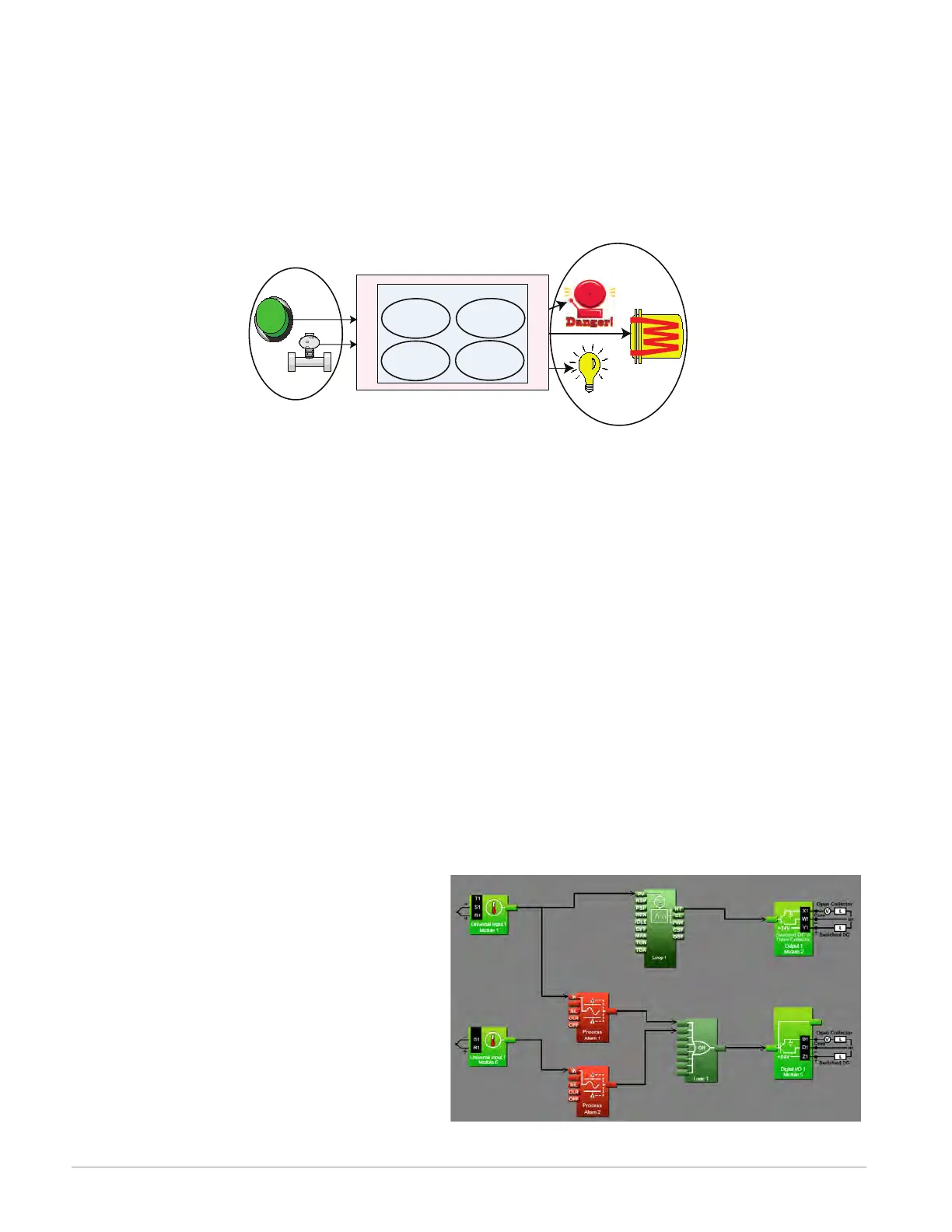
In the graphic below the following is true:
• Universal Input 1 is connected to the Process Value (PV) input of the control loop.
• When the control loop sees that the
PV is less than the user defined set
point it will drive the output to the
load through its heat (HT) output.
• Two unique high process alarms are
configured to monitor Universal Inputs
1 and 2.
• The logic function block (FB) is con-
figured as an OR where its output
will come on if either input comes on
driving the real-world digital output
(alarm) it's connected to.
Functions
Outputs
Process
Alarm
High
PID
Heat
Power
Sequencing
Outputs
Silence
Alarms
Inputs