Watlow F4T • 136 • Chapter 5 Function Reference
High Power Scale
Set the maximum power level for the output. When the input (Rcvr) is 100% (on), the output
is equal to the value set here. When the input is 0% (off), the output is equal to the value set
with Low Power Scale. Values between 0% and 100% are scaled proportionally.
Range: 0.0 to 100.0%
Electromechanical and NO-ARC Relays
Use this block to drive a digital output in the controller to switch an external device. These
blocks are found on the canvas in the Function Block Diagram editor. The number of these
blocks available depends on the number of electromechanical and NO-ARC relays on the flex
modules installed in the controller.
Signals
Direction
Label Type Function
Receiver
- - - -
Analog %
or Digital
Off or 0%: the output is off.
Between 0% and 100%: the output switches according to
the Fixed Time Base setting.
On or 100%: the output is on.
Name
Uniquely identify this FB using up to 20 alphanumeric characters.
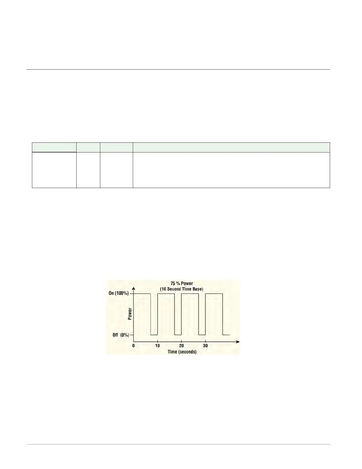
Fixed Time Base
Set the duration of one on-off cycle. A percent output power is converted to a duty cycle over
the Fixed Time Base. For example, if the Fixed Time Base is ten seconds and 75% power is
called for, the output turns on for 7.5 seconds and off for 2.5 seconds, and repeats as illustrat-
ed below. This is appropriate for mechanical relays.
Range: 5.0 to 60.0 seconds
Low Power Scale
Set the minimum power level for the output. When the input equals 0% (off), the output is
equal to the value set here. When the input equals 100% (on), the output is equal to the value
set with High Power Scale. Values between 0% and 100% are scaled proportionally. See the il-
lustration below.
Range: 0.0 to 100.0%