Watlow F4T • 153 • Chapter 5 Function Reference
Signals
Direction
Label Type Function
Receivers
- - - - Digital Input to logic function
- - - - Digital Input to logic function
- - - - Digital Input to logic function
- - - - Digital Input to logic function
- - - - Digital Input to logic function
- - - - Digital Input to logic function
- - - - Digital Input to logic function
- - - - Digital Input to logic function
Transmitter - - - - Digital True when all of the inputs are false, otherwise true
Function
To detect when all the inputs are false, set Function to Nor.
Error Handling
Use Error Handling to select the output's value and error status when the function cannot de-
finitively determine the result.
Options:
• True Good: output's value is true (on) with no error
• True Bad: output's value is true (on) and has an error
• False Good: output's value is false (off) with no error
• False Bad: output's value is false (off) and has an error
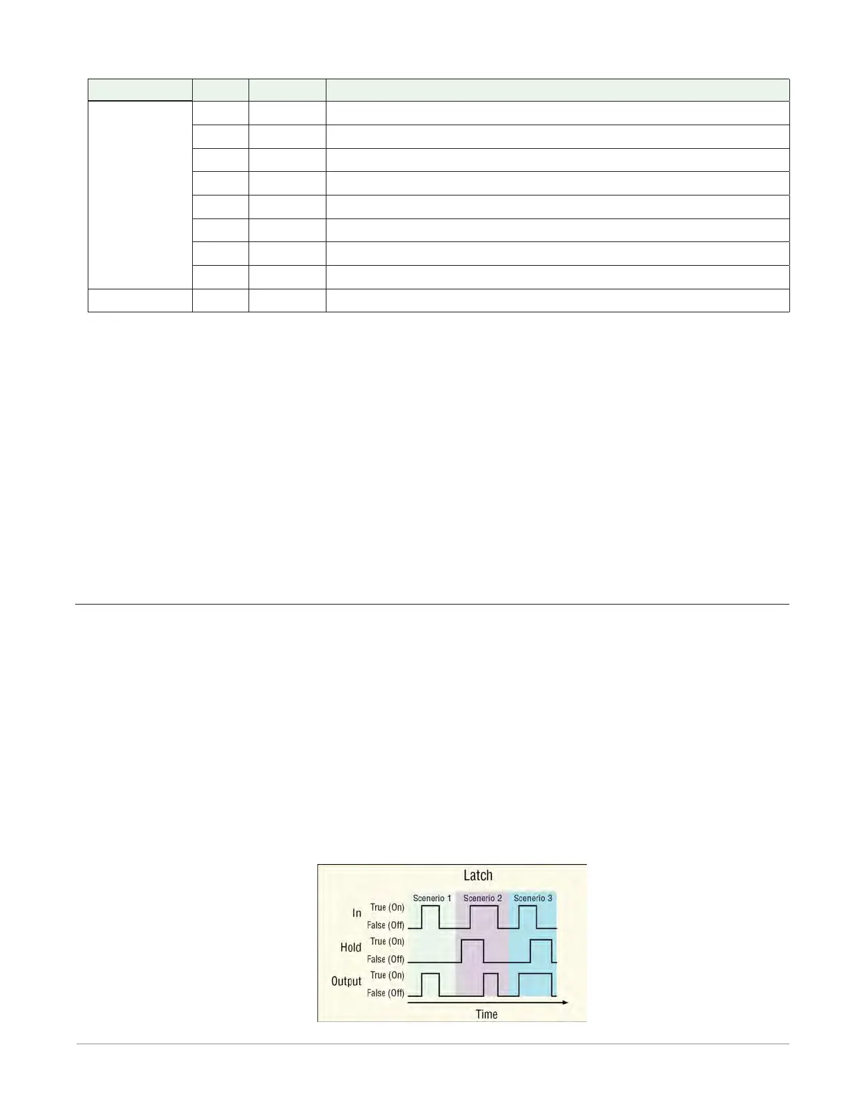
Latch
When the HOLD input is false (off, 0%), the output follows the IN input value. When HOLD is
true (on, 100%), the output does not change; it is held (latched) at the value that was present
at IN when HOLD became true (on, 100%).
To understand the Latch’s behavior consider these scenarios illustrated in the timing diagram
below:
1. When Hold is false, the output follows IN.
2. If IN becomes true after Hold become true, the output remains false until Hold becomes
false.
3. If Hold becomes true after IN becomes true, the output remains true as long as Hold is true
even after IN becomes false.