Watlow F4T • 67 • Chapter 4 Application Examples
Application Tips:
• Loop blocks are initially located in the library and can be dragged to the canvas.
• The signal from the universal input carries the process value to the PV receiver on the
loop block where it is used as feedback to the control algorithm.
• The signal from HT on the loop to the output block controls the heater by signaling
when the heater should be on for on-off control or how much it should be on with a 0
to 100% signal for PID control.
• Enter names for blocks where possible to make the application easier to understand.
• Make sure the input block’s Sensor Type and other parameters are set correctly for
your sensor.
• In the loop block set the Control Action and Heat Algorithm based on the type of load
being controlled.
• If you use the PID algorithm, you’ll need to tune the loop for your system. For more in-
formation on autotuning see the section entitled "Autotune" in Chapter 5.
• Depending on the type of output and the load it drives, you may be able to set Time
Base Type in the output block to Variable Time Base to improve control stability. Don’t
use this setting with mechanical relays or switching devices or loads that are not purely
resistive.
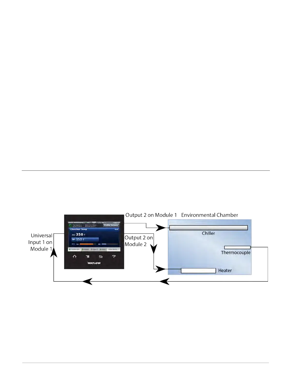
Heat and Cool Control Loop
In this example Universal Input 1 on module 1 measures the temperature of an environmental
chamber with a thermocouple. Control Loop 1 takes its feedback directly from the universal
input, and uses output 2 on module 2 to heat the chamber and output 2 on module 1 to cool
the chamber as needed.