Watlow F4T • 320 • Chapter 6 Appendix
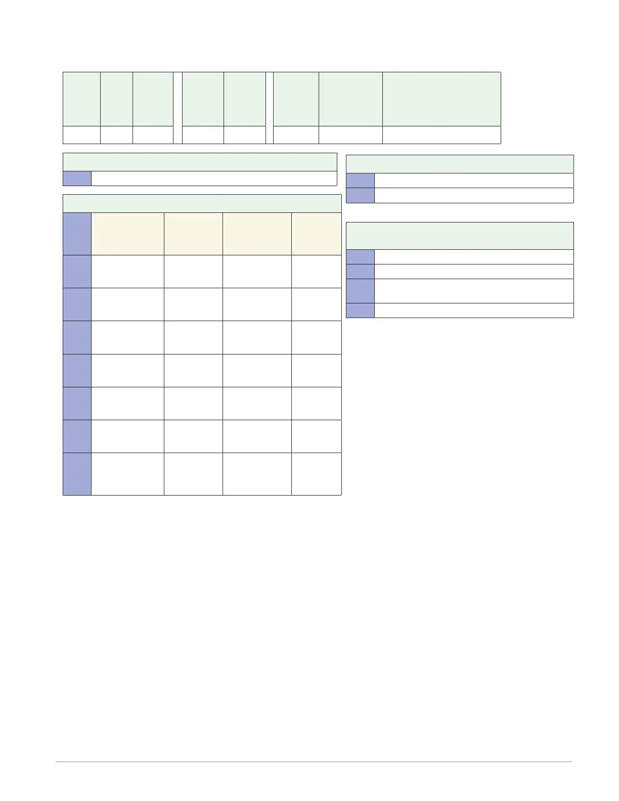
Flex Module - Limit Ordering Information
Part Number
① ② ③
Module
ID Type
④
Future
Option
-
⑤ ⑥ ⑦
Input and
Output
Hardware
⑧
Future
Option
-
⑨
Future
Options
⑩
Custom
Options and
Connectors
⑪ d
Custom Options - Firmware,
Overlay, Preset Parameters,
Locked Code
FM L A A A
③ Module Type
L = Limit
⑤ ⑥ ⑦ Input and Output Hardware
Functions
Auxiliary
Output
Hardware
Limit Output
Hardware
Auxiliary
Input
Hard-
ware
LCJ =
Limit control
with universal
input
Switched dc/
open collec-
tor
Mechanical re-
lay 5A, Form A
None
LEJ =
Limit control
with universal
input
Mechanical
relay 5A,
Form C
Mechanical re-
lay 5A, Form A
None
LAJ =
Limit control
with universal
input
None Mechanical re-
lay 5A, Form A
None
MCJ =
Limit control
with thermistor
input
Switched dc/
open collec-
tor
Mechanical re-
lay 5A, Form A
None
MEJ =
Limit control
with thermistor
input
Mechanical
relay 5A,
Form C
Mechanical re-
lay 5A, Form A
None
MAJ =
Limit control
with thermistor
input
None Mechanical re-
lay 5A, Form A
None
YEB =
Limit control
with tempera-
ture input
None Mechanical re-
lay 5A, Form C
Single
digital in-
put (limit
reset)
⑩ Custom Options and Connectors
A = Right angle screw connector (standard)
F = Front screw connector
⑪ d Custom Options - Firmware, Overlay,
Preset Parameters, Locked Code
AA = Standard with quick start guide
AB = Standard without quick start guide
AC = Replacement connectors hardware only - for
the entered model number
XX = Custom