Watlow F4T Controller • 20 • Chapter 2 Configuration Using Composer
Entering Flex Module Information Prior to Installation
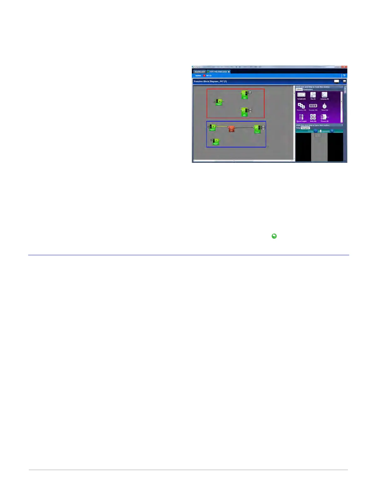
Function blocks associated with hardware will not be available until the hardware is expected
to be present. Entering a part number for any slot (even though the module is not currently
installed) allows the programmer access to the associated function blocks. As an example, if
an FMMA-UEKA-AAAA is installed in slot one,
the function blocks that would be available are
shown in the red box. After entering a part
number such as FMLA-YEBA-AAAA in slot 2, ad-
ditional hardware dependent function blocks
will appear as shown in the blue box.
Note:
When configuring modules as described
above (not installed), the controller will not
be able to control any outputs. All outputs
will be off.
To configure the controller to expect a module that is not yet installed:
1. Select the desired slot and enter a valid part number in the Expected Part Number field.
2. On the keyboard, push the Enter key.
3. Click Finish when complete to restart the controller. After the restart process is complete
the Function Block Diagram will appear.
Once the module is acquired, simply plug it into its assigned slot and click the Detect Mod-
ules button. After doing so, the controller will restart and a green flag
will be displayed for
that slot number.
Configuring the Application using the Function Block Diagram
The Function Block Diagram (FBD) view is used to connect the real-world inputs and outputs
to internal controller functions, such as alarms, control loops and ramp and soak profiling.
To enter the Function Block Diagram:
1. Click on the desired Device menu.
2. From the drop down menu click Function Block Diagram.
Topics discussed in this section follow:
Screen Orientation: detailed description of the FBD screen and associated characteristics.
Customizing the FBD Environment: change default canvas settings to user preference.
Window Anchor Points: defines a new docking location.
Getting Started: things a user will encounter on the canvas while building the application.
Selecting and Placing FBs on the Canvas: describes where to find and then place selected FBs
on the canvas.
Moving FBs on the Canvas: describes how to move selected FBs on the canvas.
Connecting FBs Together: describes how to make the application come to life by interconnect-
ing FBs.
Viewing Signal Values and Errors: describes how to view signal values and errors as they oc-
cur.