Watlow F4T • 200 • Chapter 5 Function Reference
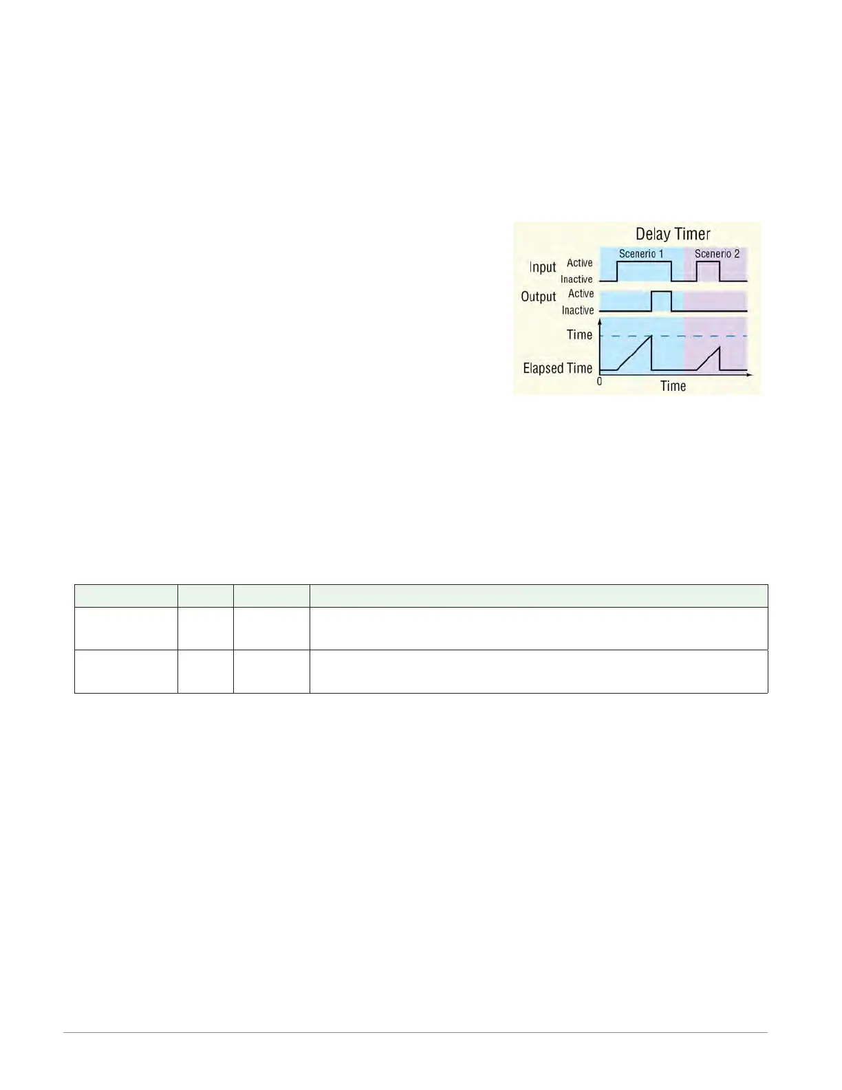
Delay
The output follows the input, but only after the input is present for at least the specified
time. This can be used to keep short input pulses from propagating through to logic or an out-
put. It can also be used to trigger a secondary action following a primary action and a specif-
ic time delay, such as, turning on successive output devices. The timer can be configured as
an on-delay or off-delay by setting the Active State and Active Level parameters appropriately.
To understand the timer’s behavior, consider these scenarios illustrated in the timing diagram
below:
1. When the input changes to its active state, the elapsed
time begins to increment. Once the elapsed time reach-
es the value set for the Time parameter, the output
changes to its active state and the elapsed time holds.
When the input changes back to its inactive state, the
output returns to its inactive state and the elapsed
time resets to zero.
2. If the input is active for less than the Time setting, the
output never becomes active.
Note:
The active and inactive states are user configurable with the parameters described below.
Therefore, the description of the timer’s behavior for its inputs and outputs refers to the
active and inactive states for each rather than on or off. For example, if the input’s ac-
tive state is set to High, the timer starts running (becomes active) when the input changes
from low (off) to high (on). However, if the input’s active state is set to Low, the timer
starts running (becomes active) when the input changes from high (on) to low (off).
Signals
Direction Label Type Function
Receiver - - - - Digital
Run signal for the timer. The timer starts when this input
becomes active.
Transmitter - - - - Digital
Becomes active once the specified time has elapsed and
becomes inactive again when the input becomes inactive.
Function
To switch the output a specified time after the input changes states, set Function to Delay.
Time
Set how long the input must be continuously active before the output becomes active.
Range: 0 to 99,999.000
Run Active Level
Set which state change at RUN starts the timer. This is the state change that is delayed.
Options:
• High: off to on
• Low: on to off