Watlow F4T • 314 • Chapter 6 Appendix
F4T Base Ordering Information
Base includes: Battery Backup, Real-Time Clock, 4.3 inch color graphical touch panel, 2 USB
host, USB configuration port, standard bus, wired Ethernet Modbus
®
TCP. SCPI protocol and
backwards compatible Modbus
®
for select key SERIES F4D/P/S parameters (see the F4T Setup
and Operation User's Guide)
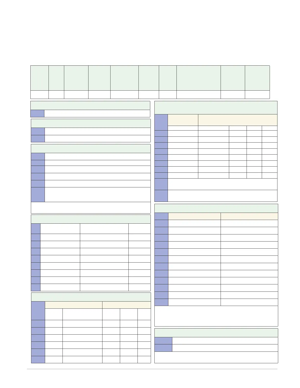
Part Number
① ② ③
Base
Type
④
Application
Type
⑤
Data
Logging
⑥
Power Supply
Connector &
Voltage, Logo
⑦
Profiles &
Function
Blocks
⑧ ⑨
Future
Options
⑩ ⑪
Documentation, Accent
Bar, Replacement
Connector & Custom
d
Control
Algorithms
⑬ ⑭ ⑮
Preloaded
Flex
Modules
F4 T AA
d Control Algorithms
Control Loop Cascade Loop
1 = 1 0
2 = 2 0
3 = 3 0
4 = 4 0
5 = 0 0
6 = 0 1
7 = 1 1
8 = 2 1
9 = 3 1
A = 0 2
B = 1 2
C = 2 2
Note: Each control loop algorithm will require 1 universal or
thermistor input from a flex module.
Note: Each cascade loop algorithm will require 2 universal or
thermistor inputs from flex modules.
⑬ ⑭ ⑮ Populated Flex Modules
AAA = No populated flex modules
XXX = Contact factory - Populated flex modules
Note: If AAA is selected you will need to order Flex Modules
(FM) next to account for input and output hardware.
⑤ Data Logging and Graphic Trend Charts
A = None
B = Graphical trend chart
J = Data logging
K = Data logging with encrypted files
L = Data logging with graphical trend chart
M* = Data logging with encrypted files, graphical trend
charts and batch processing with bar code data
entry.
*Must also order digit 7: Profiles option D, E or F for batch
processing with bar code data entry feature to be enabled.
④ Application Type
1 = Standard
X = Custom, contact factory
③ Base Type
T = Touch Screen
⑥ Power Supply Connector & Voltage, Logo
Power Supply Connector
Watlow
Logo
1 = 100 to 240Vac Right angle (standard) Ye s
2 = 100 to 240Vac Right angle (standard) No
3 = 100 to 240Vac Front screw Ye s
4 = 100 to 240Vac Front screw No
5 = 24 to 28Vac or Vdc Right angle (standard) Ye s
6 = 24 to 28Vac or Vdc Right angle (standard) No
7 = 24 to 28Vac or Vdc Front screw Ye s
8 = 24 to 28Vac or Vdc Front screw No
⑦ Profiles and Function Blocks
Profiles Function Blocks
None 40 Profiles
Basic
Set
Set 1 Set 2
A = X X
B = X X
C = X X
D = X X
E = X X
F = X X
⑩ ⑪ Documentation, Accent Bar, Replacement
Connector & Custom
Documenta-
tion
Decorated Brush Aluminium
Accent Bar
DVD/QSG Gray Blue Red
None
1A = Yes X
1B = Yes
X
1C = Yes
X
1D = Yes
X
1E = No X
1F = No
X
1G = No
X
1H = No
X
1J = Replacement connectors only - for the model number
entered
XX = Contact factory, other custom-firmware, preset
parameters, locked code, logo