Watlow F4T • 213 • Chapter 5 Function Reference
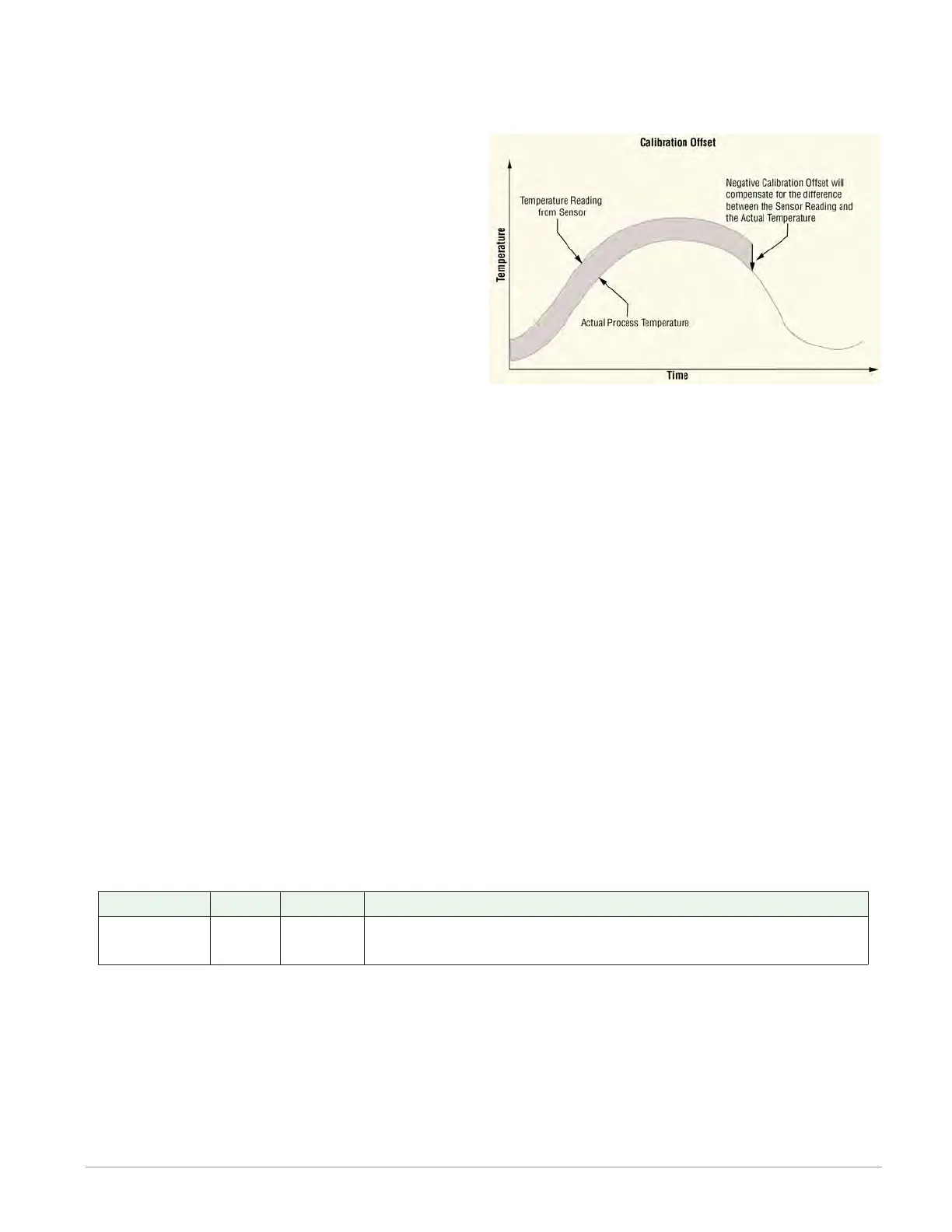
Calibration Offset
Set a value to add to the measured input value to compensate for sensor placement, lead
wire resistance or other factors that cause the input to vary from the actual process value
Range: -99,999.000 to 99,999.000°F or units
-55,555 to 55,555°C
Filter
Set the amount of filtering to apply to the in-
put. Filtering smooths signal fluctuations. In-
crease the time to increase filtering. Excessive
filtering slows the input’s response.
Range: 0.0 to 60.0 second
Input Error Latching
Set whether an input error persists until it is
cleared or clears automatically when the sensor signal returns to a normal level.
Options:
• Off: error clears automatically once the input returns to normal.
• On: error remains active until the input returns to normal and the error is cleared by
the Clear Error parameter.
Clear Error
Set this parameter to Clear to reset the input error after correcting the condition that caused
it.
Options: Ignore, Clear
1K Potentiometer
Use this sensor type to measure and scale a resistance input. These FBs are found on the
canvas of the FB diagram. The number of these FBs that are available depends on the number
of flex modules with universal inputs installed and configured for a potentiometer input.
The module number shown on the block is the number of the controller’s slot that houses the
flex module with the universal input. The Universal Input number indicates the specific input
on the flex module.
Signals
Direction Label Type Function
Transmitter - - - - Analog
Supplies scaled process value ± the offset as a connec-
tion to another FB.
Name
Uniquely identify this FB using up to 20 alphanumeric characters.
Sensor Type
To detect and condition a resistance signal for use with other FBs, set Sensor Type to Potenti-
ometer.