Watlow F4T • 324 • Chapter 6 Appendix
4 Solid-State Relays
• Two pairs of SSRs, each pair shares a common
• Form A, 24VÅ (ac) min., 264VÅ (ac) max., opto-isolated, without contact suppres-
sion, resistive load 2A per output at 240V
Å (ac), max. See table for max. current
per output
Ambient Temperature 1 Module per Base 2 or More Modules
20°C
2.00A 1.50A
50°C
1.30A 1.00A
6 Digital Input/Output Option - (6 DIO)
• Digital input update rate 10Hz
- DC voltage
- Max. input 36V @ 3mA
- Min. high state 3V at 0.25mA
- Max. low state 2V
- Dry contact
- Min. open resistance 10KΩ
- Max. closed resistance 50Ω
- Max. short circuit 13mA
• Digital output update rate 10Hz
- Output voltage 24V, current limit, Output 6 = 10mA max., Output 5 = 3 pole DIN-A-
MITE
®
or 24mA max.
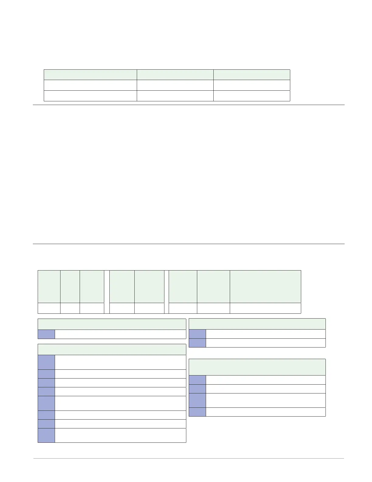
Flex Module - High Density Ordering Information
Part Number
① ② ③
Module
ID Type
④
Future
Option
-
⑤
Input and
Output
Hardware
⑥ ⑦ ⑧
Future
Option
-
⑨
Future
Options
⑩
Custom
Options and
Connectors
⑪ d
Custom Options - Firmware,
Overlay, Preset Parameters,
Locked Code
FM H A AAA A
③ Module Type
H = High Density I/O
⑤ Input and Output Hardware
R =
4 universal inputs (T/C, RTD 2-wire, 0-10VDC,
0-20mA)
P = 4 thermistor inputs
C = 6 digital I/O
F = 3 universal process/retransmit outputs
B =
3 mechanical relay 5A, 2 Form C and 1 Form A
(Form A shares a common with one Form C)
J = 4 mechanical relay 5A, Form A
K = 2 SSRs 10A
L =
4 SSRs at 2A each. SSRs grouped in 2 pairs with each
pair sharing a common
⑩ Custom Options and Connectors
A = Right angle screw connector (standard)
F = Front screw connector
⑪ d Custom Options - Firmware, Overlay,
Preset Parameters, Locked Code
AA = Standard with quick start guide
AB = Standard without quick start guide
AC = Replacement connectors hardware only - for
the entered model number
XX = Custom