Watlow F4T • 205 • Chapter 5 Function Reference
RTD 1,000 Ohm: use this sensor type to condition a temperature measurement made with an
RTD.
1K Potentiometer: use this sensor type to measure and scale a resistance input.
Universal Input Errors: this section describes the errors that may occur on the signal supplied
by the Universal Input function block.
About the Universal Input
The Universal Input block scales the electrical signal received by the analog input hardware to
a process value that can be used by other blocks such as a control loop or alarm. If the signal
is from a thermocouple or RTD, once the Sensor Type, TC Linearization and RTD Leads param-
eters are set, the block scales the signal to an absolute temperature with no other configura-
tion required.
Note:
Flex Modules can be ordered as Mixed I/O or High Density (HD) I/O. When HD modules are
in use, the pinouts on the card are slightly different than Mixed I/O modules. Pinouts and
the associated graphics are displayed for both.
Note:
Although the functionality and parameters for any given sensor type does not change with
the selected Units, the graphic does. In the following descriptions, the associated graphics
for the sensor type will be displayed for the selected units.
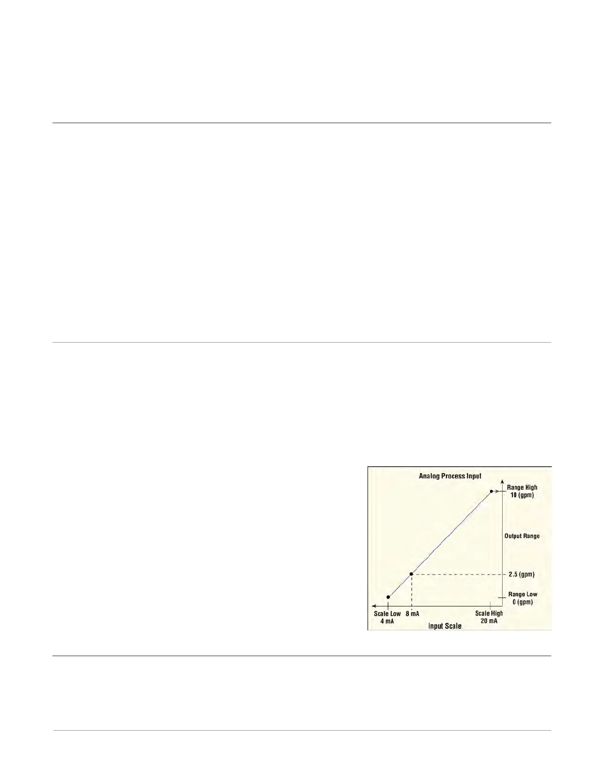
Scaling Voltage and Current Inputs to Process Units
If the signal is from a device that outputs a voltage or current proportional to the process val-
ue, set the Sensor Type, Units, Scale Low, Scale High, Range Low and Range High parameters
to present the process value in the appropriate units. Scale Low and Range Low are the coor-
dinates of one point and Scale High and Range High are the coordinates of another point de-
fining the line relating the electrical signal to the conditioned process value produced by this
block. See the figure below.
For example, a flow meter is connected to the universal input. The flow meter provides a cur-
rent signal proportional to flow where 4 mA indicates 0
gallons per minute (gpm) and 20 mA indicates 10 gpm.
With the scaling parameters set as listed below, when the
universal input receives an 8 mA signal, the output of the
block is 2.5 (gpm).
Sensor Type: Milliamps
Units: Process
Scale Low: 4 mA
Scale High: 20 mA
Range Low: 0 (gpm)
Range High: 10 (gpm)
Millivolts/Volts
These FBs are found on the canvas of the FB diagram. The number of these FBs that are avail-
able depends on the number of flex modules with Universal Inputs installed and configured for
voltage (millivolts or voltage).