Watlow F4T • 125 • Chapter 5 Function Reference
Control Loop Error
Indicates the control loop’s error status.
Options:
• None: no error
• Open Loop: the process value has not responded to the loop’s outputs as expected ac-
cording to the settings of the Open Loop Detect Deviation and Open Loop Detect Time
parameters
• Reversed Sensor: the process value has responded to the loop’s outputs by changing in
the opposite direction expected, going down during heating or up during cooling
Clear Error
Set Clear Error to Clear to reset the Control Loop Error after correcting the condition that
caused the problem.
Options: Ignore, Clear
Counter
Use a counter to set an output when a digital signal’s state changes a given number of times.
A counter can count up or down from the load value. Its output turns on when the count
equals the target value. The output turns off and the count is set equal to the load value
when the reset signal is received.
This block is found in the Function Block Diagram editor’s Library when working with a con-
troller that offers the Counter block. The number of these blocks that are available is shown
within the parenthesis.
Choose whether the counter counts up or down with the Function parameter. These options
for Function are described in detail in the following sections:
Up: Count is incremented by the CNT input.
Down: Count is decremented by the CNT input.
UP
This function counts up from the load value. The count is incremented by applying a signal
to CNT. OUT turns on when the count equals the target value. OUT turns off and the count is
set equal to the load value by RST (reset).
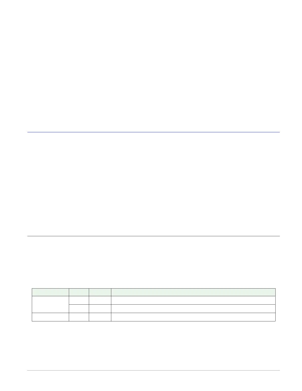
Signals
Direction Label Type Function
Receivers
CNT Digital Increments the count
RST Digital Resets the count to the load value
Transmitters OUT Digital On when the count equals the target value
Function
To increment the count with CNT, set Function to Up.