Watlow F4T • 76 • Chapter 4 Application Examples
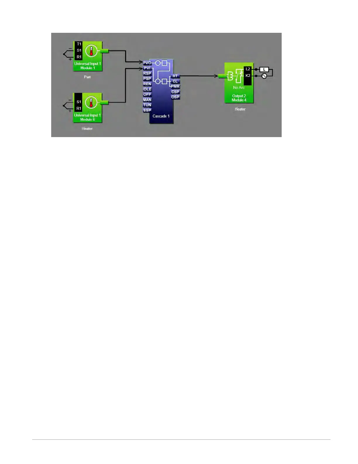
Function Block Diagram
Application Tips:
• The cascade block is initially located in the library and can be dragged to the canvas.
• The signal from the input for the part sensor to PVO on the cascade block lets the cas-
cade algorithm know the temperature of the part being heated and is used to deter-
mine the set point for the heater.
• The signal from the input for the heater sensor to PVI on the cascade block is the feed-
back for the inner loop which controls the heater temperature.
• The signal from HT on the cascade block to the output controls the heater.
• Make sure the input blocks’ Sensor Type settings and other parameters are set correctly
for your sensors.
• Set the Cascade block’s Function to Process.
• Set Range Low and Range High settings to limit the heater temperatures to which the
part can be exposed. Setting Range Low to 50 and Range High to 210 means that when
the temperature in the part is low, the heater set point will go as high as 210, but as
the temperature inside the part increases, the heater set point drops.
• In this example Control Action is set to Heat, the Inner Loop Heat Algorithm is set to
PID.
• The Inner loop PID settings were set by using the auto tune feature, but the outer loop
PID settings were set manually for proportional only control with a proportional band of
20 so that the heater set point is proportional to how cool the part is.
• If the oven must heat parts to many different temperatures or must heat parts over
a larger range of temperatures consider using the Deviation setting for the Cascade
blocks’ Function.
• For more information on cascade control parameters see the section entitled "Cascade"
in Chapter 5.