Maintenance1715−1/A1
Winterthur Gas & Diesel Ltd.
2/ 2
2. Tension Checks
1) Clean the threads of the bolts (2, Fig. 1) and the seating surfaces.
2) Apply Molykote G paste to the threads of the bolts (2).
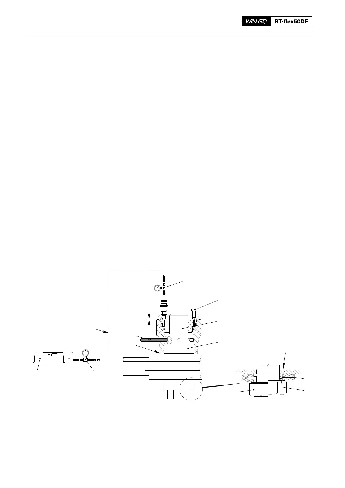
3) Refer to 9403−2 and 9403−4 . Attach the pre-tensioner and the applicable
equipment as shown in Fig. 2.
4) Operate the HP oil pump (94931) to get a pressure of 310 bar.
5) Put the feeler gauge (94122) through the slot (6) to do a check for clearance
between the nut (3) and its seating. If there is no clearance, the bolt tension has
not changed and you can do step a) and step b). If there is a clearance, do
step 6).
a) Operate the vent screw (1) to release the pressure to zero.
b) Remove the tools and equipment.
6) If there is clearance, the tension of the bolt has changed since the last check and you
must do step a) to step d) below:
a) Use a round bar (7) to tighten the nut (3).
b) Use the feeler gauge (94122) to make sure there is no clearance.
c) Operate the vent screw (1) to release the pressure to zero.
d) Remove the tools and equipment.
Note: The data to loosen the bolts is given in 9403−4.
1
94931
94935
94934A
94934A
2
x
012.902/05
3
7
6
Fig. 2
2
017.672/08
4
5
Note: Disc springs
must be compressed
1 Vent screw 5 Ring
2 Bolt 6 Slot
3 Nut 7 Round bar
4 Disc spring
2016
Engine Stays with Friction Shims: Tension Checks