Maintenance2140−1/A1
Winterthur Gas & Diesel Ltd.
10/ 14
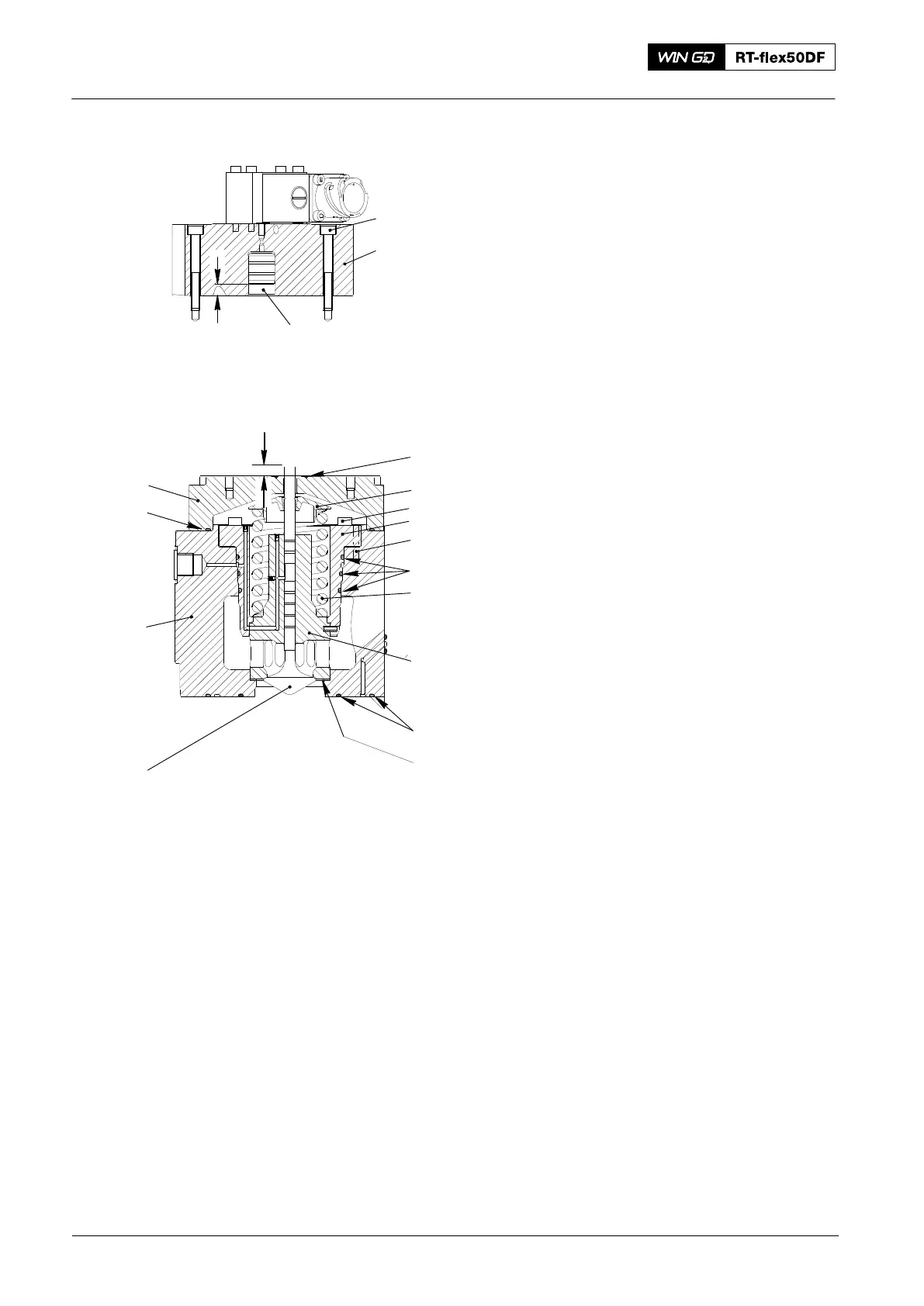
8. Assemble
Note: During this procedure, make sure
that you do not cause damage to
the surface of the valve housing
and the O-rings (9, Fig. 8).
1) Clean all parts and bores.
2) Make sure that the O-rings (9) are in
good condition.
3) Apply oil to the O-rings (9).
4) Replace the gasket (13).
5) Put the new O-rings (12) in the valve
housing (16).
6) Put the items that follow into the valve
housing (16):
D Guide bush (7)
D Spring dowel pin (8)
D Valve spring (10)
D Spring carrier (5)
D Valve spindle (15).
Note: The valve cotter is installed, see
paragraph 5.
7) Apply Never-Seez High Temperature
Stainless lubricant to the threads and
surfaces of the six Allen screws (6).
8) Torque symmetrically the six Allen
screws (6) to 10 Nm.
9) Measure the distance A between the
end of the valve spindle (14) and the
cover (17). The distance must be
8.5 mm.
10) Clean the piston hole in the cover (2).
11) Apply lubricating oil to the piston (3).
12) Put the piston (3) fully into the
cover (2).
13) Measure the piston stroke B.
14) Calculate the valve clearance B − A.
D The valve clearance B − A must be
between 0.20 mm and 1.22 mm. If the
value is too low, the valve will not fully
close.
15) Apply oil to the new O-ring (16).
16) Put the O-ring (15) into the cover (17).
17) Attach the cover (17) to the valve
housing (15).
2016
Gas Admission Valve: Removal, Disassemble, Assemble, Checks, Installation
Fig. 7
3
1
2
B
WCH03493
11
5
10
8
4
7
9
13
12
14
17
15
16
A
6