Maintenance2140−1/A1
Winterthur Gas & Diesel Ltd.
12/ 14
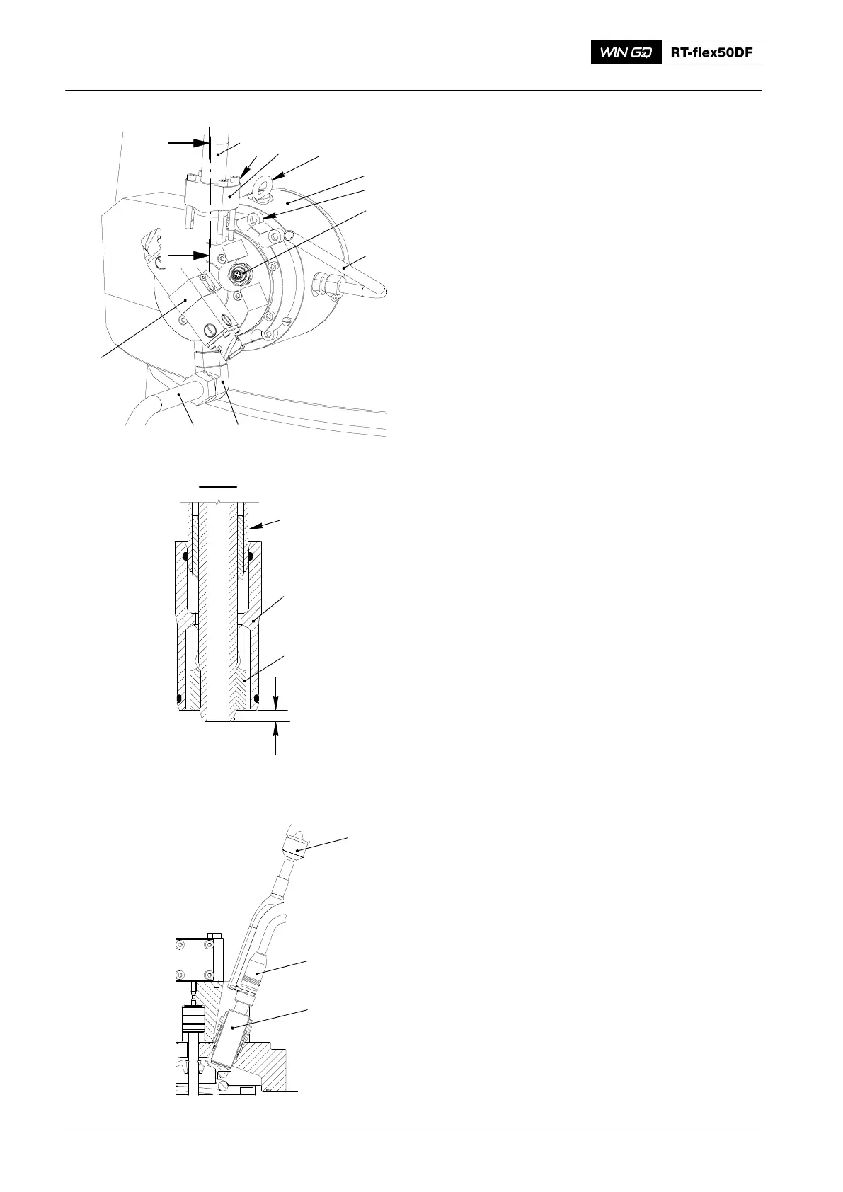
9. Installation
1) Attach the eye bolt (94040−M8, Fig. 10)
to the housing of the GAV (4).
2) Lift and move the GAV (4) to the
applicable position at the cylinder liner.
3) Make sure that all surfaces that will
touch are clean.
4) Apply Never Seez High Temperature
Stainless lubricant to the four Allen
screws (5).
5) Torque the four Allen screws to 40 Nm.
6) Attach the drain pipe (9) and the
adjustable angle union (8) to the
GAV (4).
7) Attach the lubricating oil pipe (7) to the
GAV.
8) Make sure that the sealing face of the
oil pipe (1) has no damage. If there is
damage, grind the sealing faces (refer
to 8460−1).
9) Adjust the claw (11) with an
open-ended wrench until there is a
distance of 5.5mm between the claw
and the end of the pipe (1) .
10) Attach the flange (3) and the
high-pressure hydraulic pipe (1) to the
GAV (4).
11) Apply oil to the threads and surfaces
that touch of the four Allen screws (2).
12) Torque the four Allen screws (2) to
20 Nm.
13) Connect the electrical connections to
the rail valve (10).
14) Use the tool (94023A, Fig. 11) to attach
the electrical connection (1) to the
valve stroke sensor (2).
2016
Gas Admission Valve: Removal, Disassemble, Assemble, Checks, Installation
Fig. 9
94040−M8
2
3
1
5
6
7
4
8
9
10
WCH03394
94023A
Fig. 10
1
2
I
I
I - I
5.5 mm
WCH03494
1
11
3